SLAAEO3 September 2024 MSPM0L2227 , MSPM0L2228
4.2.1 Charge Pump
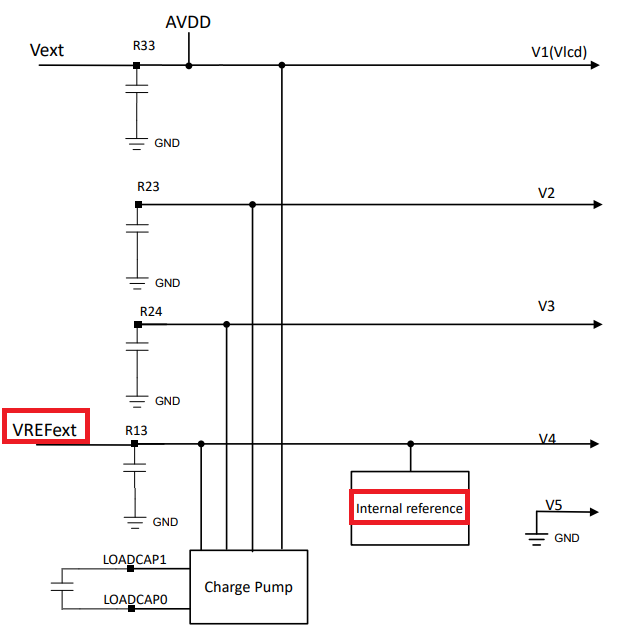
The VLCD voltage sets the voltage level of V1, the highest LCD voltage in the waveforms. This is set in software that is sourced from the AVDD, the internal charge pump, or an external source. MSPM0 LCD module includes a built-in charge pump.
There are several advantages of using a charge pump for generating the VLCD voltage. Firstly, the charge pump provides a regulated voltage to the LCD to keep a stable voltage output for the display. Next, using a charge pump allows for the VLCD to be set to a different voltage level that is independent of DVCC. Therefore, the VLCD is set at the best level for the particular LCD display, and keeps good contrast, even as the battery in the system drains.
The built-in charge pump has programmable voltage levels for use with different segmented displays. The allowed maximum operating voltage comes from the design of the particular LCD glass. Setting a different VLCD changes the contrast ratio, so having software-configurable voltage levels from the charge pump allows contrast control through software. For example, using a lower VLCD provides less contrast, but also has less current consumption; the user is able to experiment with this trade-off in the final design.
The charge pump requires an external capacitor for operation. The charge pump capacitor on the MSPM0 LCD module is connected between two pins instead of directly to ground, so the capacitor not being present is not damaged the MCU (though the charge pump does not work properly).
When charge pump is referenced from internal reference source, the internal reference circuit is able to operate in one of two modes, continuous or sampled. In the continuous mode, a continuous reference is generated if the LCDREFEN bit is set. In sampled mode, the voltage on the R13 pin is maintained by a capacitor for lower power consumption.
Reference the charge pump to follow an external source. Using an external source is useful if multiple MSPM0 MCUs are used together to control a single larger segmented display that is controlled with a single device.
 Figure 4-4 Charge Pump Reference