SLAAEO3 September 2024 MSPM0L2227 , MSPM0L2228
4.6 Low Power Mode Feature
MSPM0 LCD modules are designed with low power as a key feature. In addition to some of the low power options discussed in the earlier sections (such as the adjustable charge pump voltage level, and options for external biasing), the charge pump is only turned on for a small percentage of the overall operation of the module. The charge pump runs with a low duty cycle so that its peak current is only seen for a very small portion of the overall time that the LCD is on; this means that the LCD keeps a very low average current.
The peak charge pump current is found in the data sheet for the particular device. There is also usually a specification for the time to charge the CLCD charge pump cap when the cap is discharged, the peak current and the charge time help to determine an average current for the LCD module. The worst case is when the charge pump is at the peak current ICC,Peak,CP for the time tLCD,CP,on when CLCD has been discharged. The rest of the time, the module is in a much lower current state. In addition, using a low-leakage capacitor for CLCD helps to reduce the energy consumption as the charge pump runs with a lower duty cycle.
 Figure 4-9 Low Charge Pump Duty Cycle
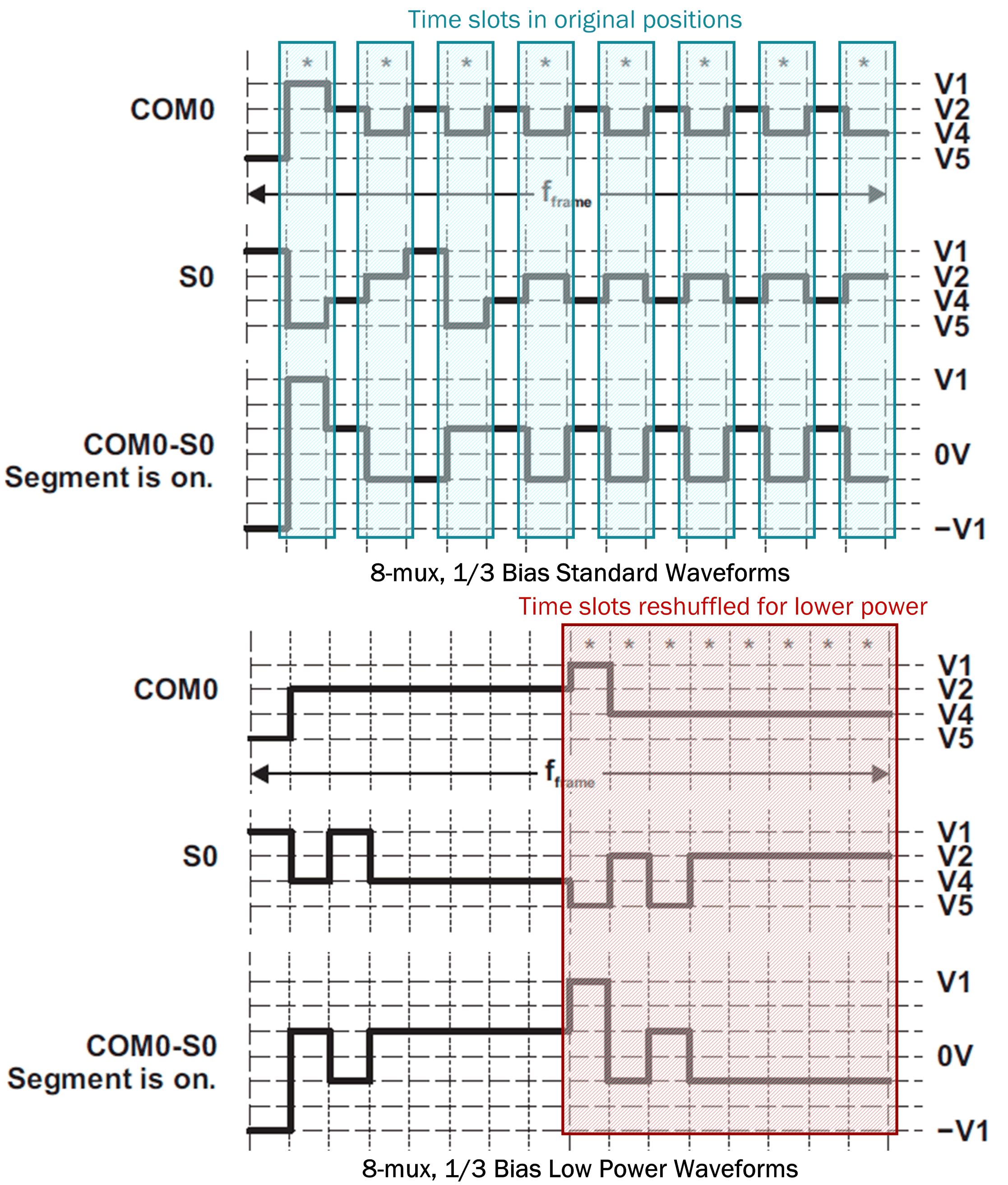
MSPM0 LCD module also has a setting for using lower power versions of the LCD waveforms. The lower power versions of the waveforms have the voltage sequence re-shuffled so that certain time slots are grouped together. This makes for fewer switching events on each pin and lower current consumption. By reducing the number of toggles on the switch controls in a given LCD frame, the power consumption is reduced. Figure 4-10 shows an example of the normal and lower power versions of waveforms for 8-mux mode.
 Figure 4-10 Low-Power Waveforms Example
The LCD module is operational in all power modes except SHUTDOWN mode, allowing for a new level of ultra-low power and enabling new LCD applications where the power supply is very limited. See the device-specific data sheet for more details about LCD current consumption in low-power modes.