SLAAEQ2 September 2024 MSPM0G1506 , MSPM0G3507
- 1
- Abstract
- Trademarks
- 1Introduction
-
2Example Mitigation Control Board Design
- 2.1 Overview of Mitigation Board Functions
- 2.2 Audible and Visible Detection Alarm
- 2.3 Freeze Detection (Water-Based Systems)
- 2.4 Isolation and or Safety Shut-off Valves (SSOVs) in the Refrigeration System to Limit Releasable Charge
- 2.5 Electronic Controls With A2L Logic to Perform Required Actions in The Event of a Leak — Such as Shutting off the Compressor and or Other Components
- 2.6 Ventilation and or Circulation Fans Within Cases or Walk-in Units
- 3Summary
- 4References
2.5 Electronic Controls With A2L Logic to Perform Required Actions in The Event of a Leak — Such as Shutting off the Compressor and or Other Components
If leak is detected, the following actions must be taken and continued for at least 5 minutes after the refrigerant detection system has reset:
- Indoor blower fan is switched on
- Fully open all zoning dampers on appliance and energize control signals for external zoning dampers if applicable
- Disable the compressor operation, unless compressor operation reduces the leakage rate, or the total amount released in the indoor space
TI collateral for designers: 24-VAC Multi-Channel Solid State Relay Reference Design Using Digital Isolator.
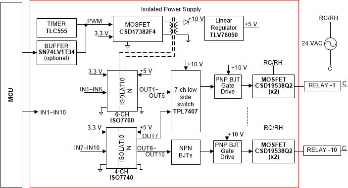
Design Overview: This reference design features a multi-channel solid-state relay (SSR) using a single isolation. It employs a multi-channel digital isolator with a common ground gate-drive circuit and a single isolated power supply to independently control multiple SSRs. The design supports 24-VAC relays with up to 2A current, scalable to 240 VAC and higher currents. Each SSR channel is compact, consuming less than 75mm² with a maximum component height of 3mm. The single isolated power supply minimizes board space and reduces BOM cost compared to electromechanical relays.
 Figure 2-12 TIDA-010085 Reference Design
Block Diagram
Figure 2-12 TIDA-010085 Reference Design
Block DiagramFeatures:
- Multiple solid-state relays using a single isolation with multichannel digital isolator, easily scalable to any number of SSR channels with minimum extra cost
- SSR drive voltage 24 VAC ±20%, drive current 2A RMS (voltage and current rating, scalable by using appropriately rated components)
- SSR turn on and turn off time: 15–300 μs (adjustable), average current consumption per SSR drive (referred to primary) < 4mA (adjustable down to 20μA per channel)
- SSR size < 75mm2 per channel. Height is around 3mm.
- Functionally isolated open-loop flyback-based power supply without the need of an MCU
- Surge and switching overvoltage protection