SLAU144K December 2004 – August 2022 MSP430AFE221 , MSP430AFE222 , MSP430AFE223 , MSP430AFE231 , MSP430AFE232 , MSP430AFE233 , MSP430AFE251 , MSP430AFE252 , MSP430AFE253 , MSP430F2001 , MSP430F2002 , MSP430F2003 , MSP430F2011 , MSP430F2012 , MSP430F2013 , MSP430F2101 , MSP430F2111 , MSP430F2112 , MSP430F2121 , MSP430F2122 , MSP430F2131 , MSP430F2132 , MSP430F2132-EP , MSP430F2232 , MSP430F2234 , MSP430F2252 , MSP430F2252-Q1 , MSP430F2254 , MSP430F2272 , MSP430F2272-Q1 , MSP430F2274 , MSP430F2274-EP , MSP430F233 , MSP430F2330 , MSP430F235 , MSP430F2350 , MSP430F2370 , MSP430F2410 , MSP430F2416 , MSP430F2417 , MSP430F2418 , MSP430F2419 , MSP430F247 , MSP430F2471 , MSP430F248 , MSP430F2481 , MSP430F249 , MSP430F2491 , MSP430F2616 , MSP430F2617 , MSP430F2618 , MSP430F2619 , MSP430G2001 , MSP430G2101 , MSP430G2102 , MSP430G2111 , MSP430G2112 , MSP430G2121 , MSP430G2131 , MSP430G2132 , MSP430G2152 , MSP430G2153 , MSP430G2201 , MSP430G2201-Q1 , MSP430G2202 , MSP430G2203 , MSP430G2210 , MSP430G2211 , MSP430G2212 , MSP430G2213 , MSP430G2221 , MSP430G2230 , MSP430G2231 , MSP430G2231-Q1 , MSP430G2232 , MSP430G2233 , MSP430G2252 , MSP430G2253 , MSP430G2302 , MSP430G2303 , MSP430G2312 , MSP430G2313 , MSP430G2332 , MSP430G2333 , MSP430G2352 , MSP430G2353 , MSP430G2402 , MSP430G2403 , MSP430G2412 , MSP430G2413 , MSP430G2432 , MSP430G2433 , MSP430G2444 , MSP430G2452 , MSP430G2453 , MSP430G2513 , MSP430G2533 , MSP430G2544 , MSP430G2553 , MSP430G2744 , MSP430G2755 , MSP430G2855 , MSP430G2955 , MSP430TCH5E
- Read This First
- 1 Introduction
- 2 System Resets, Interrupts, and Operating Modes
-
3 CPU
- 3.1 CPU Introduction
- 3.2 CPU Registers
- 3.3 Addressing Modes
- 3.4
Instruction Set
- 3.4.1 Double-Operand (Format I) Instructions
- 3.4.2 Single-Operand (Format II) Instructions
- 3.4.3 Jumps
- 3.4.4 Instruction Cycles and Lengths
- 3.4.5 Instruction Set Description
- 3.4.6
Instruction Set Details
- 3.4.6.1 ADC
- 3.4.6.2 ADD
- 3.4.6.3 ADDC
- 3.4.6.4 AND
- 3.4.6.5 BIC
- 3.4.6.6 BIS
- 3.4.6.7 BIT
- 3.4.6.8 BR, BRANCH
- 3.4.6.9 CALL
- 3.4.6.10 CLR
- 3.4.6.11 CLRC
- 3.4.6.12 CLRN
- 3.4.6.13 CLRZ
- 3.4.6.14 CMP
- 3.4.6.15 DADC
- 3.4.6.16 DADD
- 3.4.6.17 DEC
- 3.4.6.18 DECD
- 3.4.6.19 DINT
- 3.4.6.20 EINT
- 3.4.6.21 INC
- 3.4.6.22 INCD
- 3.4.6.23 INV
- 3.4.6.24 JC, JHS
- 3.4.6.25 JEQ, JZ
- 3.4.6.26 JGE
- 3.4.6.27 JL
- 3.4.6.28 JMP
- 3.4.6.29 JN
- 3.4.6.30 JNC, JLO
- 3.4.6.31 JNE, JNZ
- 3.4.6.32 MOV
- 3.4.6.33 NOP
- 3.4.6.34 POP
- 3.4.6.35 PUSH
- 3.4.6.36 RET
- 3.4.6.37 RETI
- 3.4.6.38 RLA
- 3.4.6.39 RLC
- 3.4.6.40 RRA
- 3.4.6.41 RRC
- 3.4.6.42 SBC
- 3.4.6.43 SETC
- 3.4.6.44 SETN
- 3.4.6.45 SETZ
- 3.4.6.46 SUB
- 3.4.6.47 SUBC, SBB
- 3.4.6.48 SWPB
- 3.4.6.49 SXT
- 3.4.6.50 TST
- 3.4.6.51 XOR
-
4 CPUX
- 4.1 CPU Introduction
- 4.2 Interrupts
- 4.3 CPU Registers
- 4.4 Addressing Modes
- 4.5
MSP430 and MSP430X Instructions
- 4.5.1 MSP430 Instructions
- 4.5.2
MSP430X Extended Instructions
- 4.5.2.1 Register Mode Extension Word
- 4.5.2.2 Non-Register Mode Extension Word
- 4.5.2.3 Extended Double-Operand (Format I) Instructions
- 4.5.2.4 Extended Single-Operand (Format II) Instructions
- 4.5.2.5 Extended Emulated Instructions
- 4.5.2.6 MSP430X Address Instructions
- 4.5.2.7 MSP430X Instruction Execution
- 4.6
Instruction Set Description
- 4.6.1 Extended Instruction Binary Descriptions
- 4.6.2
MSP430 Instructions
- 4.6.2.1 ADC
- 4.6.2.2 ADD
- 4.6.2.3 ADDC
- 4.6.2.4 AND
- 4.6.2.5 BIC
- 4.6.2.6 BIS
- 4.6.2.7 BIT
- 4.6.2.8 BR, BRANCH
- 4.6.2.9 CALL
- 4.6.2.10 CLR
- 4.6.2.11 CLRC
- 4.6.2.12 CLRN
- 4.6.2.13 CLRZ
- 4.6.2.14 CMP
- 4.6.2.15 DADC
- 4.6.2.16 DADD
- 4.6.2.17 DEC
- 4.6.2.18 DECD
- 4.6.2.19 DINT
- 4.6.2.20 EINT
- 4.6.2.21 INC
- 4.6.2.22 INCD
- 4.6.2.23 INV
- 4.6.2.24 JC, JHS
- 4.6.2.25 JEQ, JZ
- 4.6.2.26 JGE
- 4.6.2.27 JL
- 4.6.2.28 JMP
- 4.6.2.29 JN
- 4.6.2.30 JNC, JLO
- 4.6.2.31 JNZ, JNE
- 4.6.2.32 MOV
- 4.6.2.33 NOP
- 4.6.2.34 POP
- 4.6.2.35 PUSH
- 4.6.2.36 RET
- 4.6.2.37 RETI
- 4.6.2.38 RLA
- 4.6.2.39 RLC
- 4.6.2.40 RRA
- 4.6.2.41 RRC
- 4.6.2.42 SBC
- 4.6.2.43 SETC
- 4.6.2.44 SETN
- 4.6.2.45 SETZ
- 4.6.2.46 SUB
- 4.6.2.47 SUBC
- 4.6.2.48 SWPB
- 4.6.2.49 SXT
- 4.6.2.50 TST
- 4.6.2.51 XOR
- 4.6.3
MSP430X Extended Instructions
- 4.6.3.1 ADCX
- 4.6.3.2 ADDX
- 4.6.3.3 ADDCX
- 4.6.3.4 ANDX
- 4.6.3.5 BICX
- 4.6.3.6 BISX
- 4.6.3.7 BITX
- 4.6.3.8 CLRX
- 4.6.3.9 CMPX
- 4.6.3.10 DADCX
- 4.6.3.11 DADDX
- 4.6.3.12 DECX
- 4.6.3.13 DECDX
- 4.6.3.14 INCX
- 4.6.3.15 INCDX
- 4.6.3.16 INVX
- 4.6.3.17 MOVX
- 4.6.3.18 POPM
- 4.6.3.19 PUSHM
- 4.6.3.20 POPX
- 4.6.3.21 PUSHX
- 4.6.3.22 RLAM
- 4.6.3.23 RLAX
- 4.6.3.24 RLCX
- 4.6.3.25 RRAM
- 4.6.3.26 RRAX
- 4.6.3.27 RRCM
- 4.6.3.28 RRCX
- 4.6.3.29 RRUM
- 4.6.3.30 RRUX
- 4.6.3.31 SBCX
- 4.6.3.32 SUBX
- 4.6.3.33 SUBCX
- 4.6.3.34 SWPBX
- 4.6.3.35 SXTX
- 4.6.3.36 TSTX
- 4.6.3.37 XORX
- 4.6.4 MSP430X Address Instructions
-
5 Basic Clock Module+
- 5.1 Basic Clock Module+ Introduction
- 5.2
Basic Clock Module+ Operation
- 5.2.1 Basic Clock Module+ Features for Low-Power Applications
- 5.2.2 Internal Very-Low-Power Low-Frequency Oscillator (VLO)
- 5.2.3 LFXT1 Oscillator
- 5.2.4 XT2 Oscillator
- 5.2.5 Digitally Controlled Oscillator (DCO)
- 5.2.6 DCO Modulator
- 5.2.7 Basic Clock Module+ Fail-Safe Operation
- 5.2.8 Synchronization of Clock Signals
- 5.3 Basic Clock Module+ Registers
-
6 DMA Controller
- 6.1 DMA Introduction
- 6.2
DMA Operation
- 6.2.1 DMA Addressing Modes
- 6.2.2 DMA Transfer Modes
- 6.2.3 Initiating DMA Transfers
- 6.2.4 Stopping DMA Transfers
- 6.2.5 DMA Channel Priorities
- 6.2.6 DMA Transfer Cycle Time
- 6.2.7 Using DMA With System Interrupts
- 6.2.8 DMA Controller Interrupts
- 6.2.9 Using the USCI_B I2C Module with the DMA Controller
- 6.2.10 Using ADC12 with the DMA Controller
- 6.2.11 Using DAC12 With the DMA Controller
- 6.2.12 Writing to Flash With the DMA Controller
- 6.3 DMA Registers
-
7 Flash Memory Controller
- 7.1 Flash Memory Introduction
- 7.2 Flash Memory Segmentation
- 7.3
Flash Memory Operation
- 7.3.1 Flash Memory Timing Generator
- 7.3.2 Erasing Flash Memory
- 7.3.3 Writing Flash Memory
- 7.3.4 Flash Memory Access During Write or Erase
- 7.3.5 Stopping a Write or Erase Cycle
- 7.3.6 Marginal Read Mode
- 7.3.7 Configuring and Accessing the Flash Memory Controller
- 7.3.8 Flash Memory Controller Interrupts
- 7.3.9 Programming Flash Memory Devices
- 7.4 Flash Registers
-
8 Digital I/O
- 8.1 Digital I/O Introduction
- 8.2 Digital I/O Operation
- 8.3 Digital I/O Registers
- 9 Supply Voltage Supervisor (SVS)
- 10Watchdog Timer+ (WDT+)
- 11Hardware Multiplier
- 12Timer_A
- 13Timer_B
- 14Universal Serial Interface (USI)
-
15Universal Serial Communication Interface, UART Mode
- 15.1 USCI Overview
- 15.2 USCI Introduction: UART Mode
- 15.3
USCI Operation: UART Mode
- 15.3.1 USCI Initialization and Reset
- 15.3.2 Character Format
- 15.3.3 Asynchronous Communication Formats
- 15.3.4 Automatic Baud Rate Detection
- 15.3.5 IrDA Encoding and Decoding
- 15.3.6 Automatic Error Detection
- 15.3.7 USCI Receive Enable
- 15.3.8 USCI Transmit Enable
- 15.3.9 UART Baud Rate Generation
- 15.3.10 Setting a Baud Rate
- 15.3.11 Transmit Bit Timing
- 15.3.12 Receive Bit Timing
- 15.3.13 Typical Baud Rates and Errors
- 15.3.14 Using the USCI Module in UART Mode with Low Power Modes
- 15.3.15 USCI Interrupts
- 15.4 USCI Registers: UART Mode
-
16Universal Serial Communication Interface, SPI Mode
- 16.1 USCI Overview
- 16.2 USCI Introduction: SPI Mode
- 16.3 USCI Operation: SPI Mode
- 16.4 USCI Registers: SPI Mode
-
17Universal Serial Communication Interface, I2C Mode
- 17.1 USCI Overview
- 17.2 USCI Introduction: I2C Mode
- 17.3
USCI Operation: I2C Mode
- 17.3.1 USCI Initialization and Reset
- 17.3.2 I2C Serial Data
- 17.3.3 I2C Addressing Modes
- 17.3.4 I2C Module Operating Modes
- 17.3.5 I2C Clock Generation and Synchronization
- 17.3.6 Using the USCI Module in I2C Mode with Low-Power Modes
- 17.3.7 USCI Interrupts in I2C Mode
- 17.4 USCI Registers: I2C Mode
-
18USART Peripheral Interface, UART Mode
- 18.1 USART Introduction: UART Mode
- 18.2 USART Operation: UART Mode
- 18.3 USART Registers – UART Mode
- 19USART Peripheral Interface, SPI Mode
- 20OA
- 21Comparator_A+
-
22ADC10
- 22.1 ADC10 Introduction
- 22.2
ADC10 Operation
- 22.2.1 10-Bit ADC Core
- 22.2.2 ADC10 Inputs and Multiplexer
- 22.2.3 Voltage Reference Generator
- 22.2.4 Auto Power-Down
- 22.2.5 Sample and Conversion Timing
- 22.2.6 Conversion Modes
- 22.2.7 ADC10 Data Transfer Controller
- 22.2.8 Using the Integrated Temperature Sensor
- 22.2.9 ADC10 Grounding and Noise Considerations
- 22.2.10 ADC10 Interrupts
- 22.3 ADC10 Registers
-
23ADC12
- 23.1 ADC12 Introduction
- 23.2
ADC12 Operation
- 23.2.1 12-Bit ADC Core
- 23.2.2 ADC12 Inputs and Multiplexer
- 23.2.3 Voltage Reference Generator
- 23.2.4 Sample and Conversion Timing
- 23.2.5 Conversion Memory
- 23.2.6 ADC12 Conversion Modes
- 23.2.7 Using the Integrated Temperature Sensor
- 23.2.8 ADC12 Grounding and Noise Considerations
- 23.2.9 ADC12 Interrupts
- 23.3 ADC12 Registers
- 24TLV Structure
- 25DAC12
-
26SD16_A
- 26.1 SD16_A Introduction
- 26.2
SD16_A Operation
- 26.2.1 ADC Core
- 26.2.2 Analog Input Range and PGA
- 26.2.3 Voltage Reference Generator
- 26.2.4 Auto Power-Down
- 26.2.5 Analog Input Pair Selection
- 26.2.6 Analog Input Characteristics
- 26.2.7 Digital Filter
- 26.2.8 Conversion Memory Register: SD16MEM0
- 26.2.9 Conversion Modes
- 26.2.10 Using the Integrated Temperature Sensor
- 26.2.11 Interrupt Handling
- 26.3 SD16_A Registers
-
27SD24_A
- 27.1 SD24_A Introduction
- 27.2
SD24_A Operation
- 27.2.1 ADC Core
- 27.2.2 Analog Input Range and PGA
- 27.2.3 Voltage Reference Generator
- 27.2.4 Auto Power-Down
- 27.2.5 Analog Input Pair Selection
- 27.2.6 Analog Input Characteristics
- 27.2.7 Digital Filter
- 27.2.8 Conversion Memory Register: SD24MEMx
- 27.2.9 Conversion Modes
- 27.2.10 Conversion Operation Using Preload
- 27.2.11 Using the Integrated Temperature Sensor
- 27.2.12 Interrupt Handling
- 27.3 SD24_A Registers
- 28Embedded Emulation Module (EEM)
- Revision History
20.2.4.8 Differential Amplifier Mode
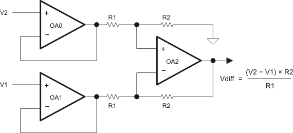
This mode allows internal routing of the OA signals for a two-opamp or three-opamp instrumentation amplifier. Figure 20-2 shows a two-opamp configuration with OA0 and OA1. In this mode the output of the OAx is connected to RTOP by routing through another OAx in the Inverting PGA mode. RBOTTOM is unconnected providing a unity gain buffer. This buffer is combined with one or two remaining OAx to form the differential amplifier. The OAx output is connected to the ADC input channel as selected by the OAxCTL0 bits.
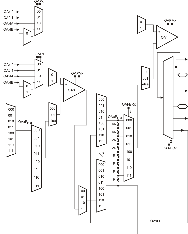
Figure 20-2 shows an example of a two-opamp differential amplifier using OA0 and OA1. The control register settings and are shown in Table 20-3. The gain for the amplifier is selected by the OAFBRx bits for OA1 and is shown in Table 20-4. The OAx interconnections are shown in Figure 20-3.
| Register | Settings (binary) |
|---|---|
| OA0CTL0 | xx xx xx 0 0 |
| OA0CTL1 | 000 111 0 x |
| OA1CTL0 | 11 xx xx x x |
| OA1CTL1 | xxx 110 0 x |
| OA1 OAFBRx | Gain |
|---|---|
| 000 | 0 |
| 001 | 1/3 |
| 010 | 1 |
| 011 | 1 2/3 |
| 100 | 3 |
| 101 | 4 1/3 |
| 110 | 7 |
| 111 | 15 |
 Figure 20-2 Two-Opamp Differential Amplifier
 Figure 20-3 Two-Opamp Differential Amplifier OAx Interconnections
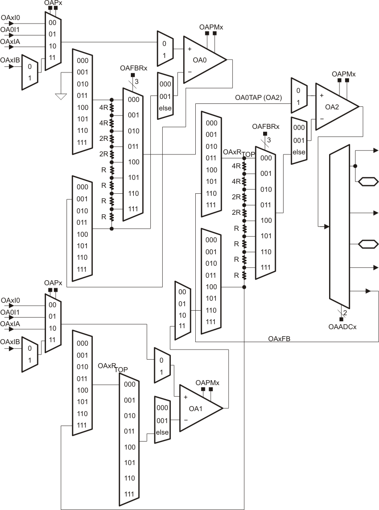
Figure 20-4 shows an example of a three-opamp differential amplifier using OA0, OA1 and OA2 (Three opamps are not available on all devices. See device-specific data sheet for implementation.). The control register settings are shown in Table 20-5. The gain for the amplifier is selected by the OAFBRx bits of OA0 and OA2. The OAFBRx settings for both OA0 and OA2 must be equal. The gain settings are shown in Table 20-6. The OAx interconnections are shown in Figure 20-5.
| Register | Settings (binary) |
|---|---|
| OA0CTL0 | xx xx xx 0 0 |
| OA0CTL1 | xxx 001 0 x |
| OA1CTL0 | xx xx xx 0 0 |
| OA1CTL1 | 000 111 0 x |
| OA2CTL0 | 11 11 xx x x |
| OA2CTL1 | xxx 110 0 x |
| OA0/OA2 OAFBRx | Gain |
|---|---|
| 000 | 0 |
| 001 | 1/3 |
| 010 | 1 |
| 011 | 1 2/3 |
| 100 | 3 |
| 101 | 4 1/3 |
| 110 | 7 |
| 111 | 15 |
 Figure 20-4 Three-Opamp Differential Amplifier
 Figure 20-5 Three-Opamp Differential Amplifier OAx Interconnections