SLAU833A May 2020 – October 2020 ADC12DJ3200
7.1 Configure the ADC EVM
Use the following steps to configure the ADC EVM.
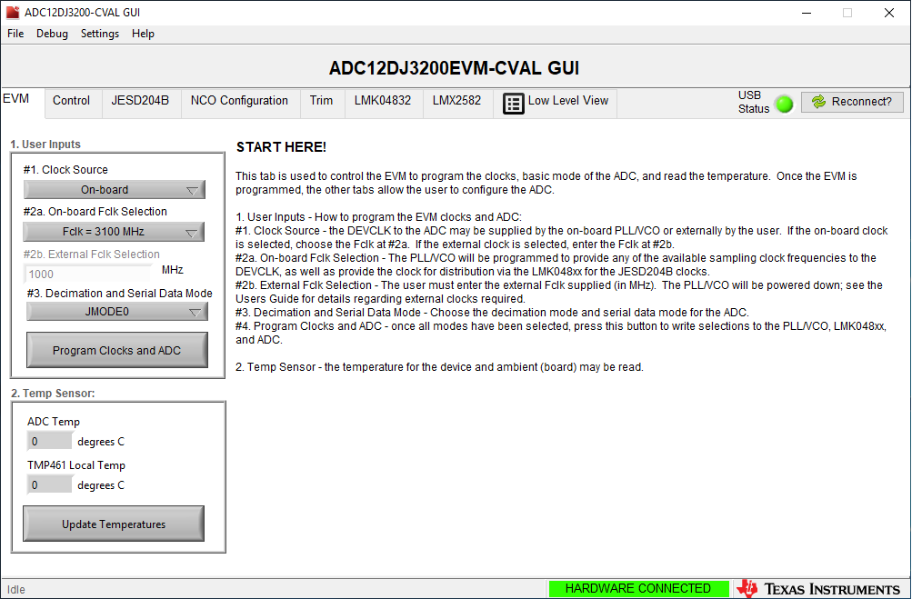
- Open ADC12DJ3200EVM-CVAL GUI, choose Fclk = 3100MHz and select JMODE0 (equivalent to 6.2 GSPS ADC sample rate and 12.4Gbps lane rate) in the EVM tab.
- Click “Program Clocks and ADC”. On the ADC EVM, verify PLL1 LCKD LED turns on. This will indicate the LMK04828 PLL1 is locked to the onboard 100-MHz VCXO.
- Figure 7-1 illustrates the GUI.
 Figure 7-1 ADC12DJ3200EVM-CVAL GUI
 - By default, the FMC+ interface EEPROM on the ADC12DJ3200EVM is installed and programmed. Please go to section 7.2.1. If using a board without this EEPROM, do the folowing steps:
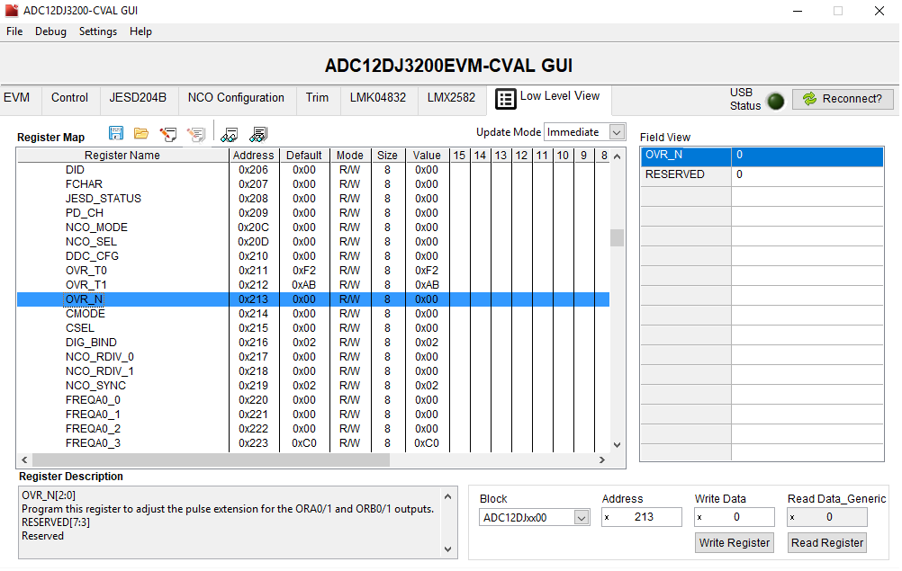
- Go to the Low Level View tab.
- In the Block box near the bottom of the page, click the drop-down arrow and select "ADC12DJxx00".
- In the Address box enter "213”, in the Write Data box write “00”, then click the Write Register button.
- Click the Read Register button to verify address 0x213 is now set to 0x00, as Figure 7-2 shows.
 Figure 7-2 Low Level View Tab