SLAU899 August 2023
3.1 Schematics
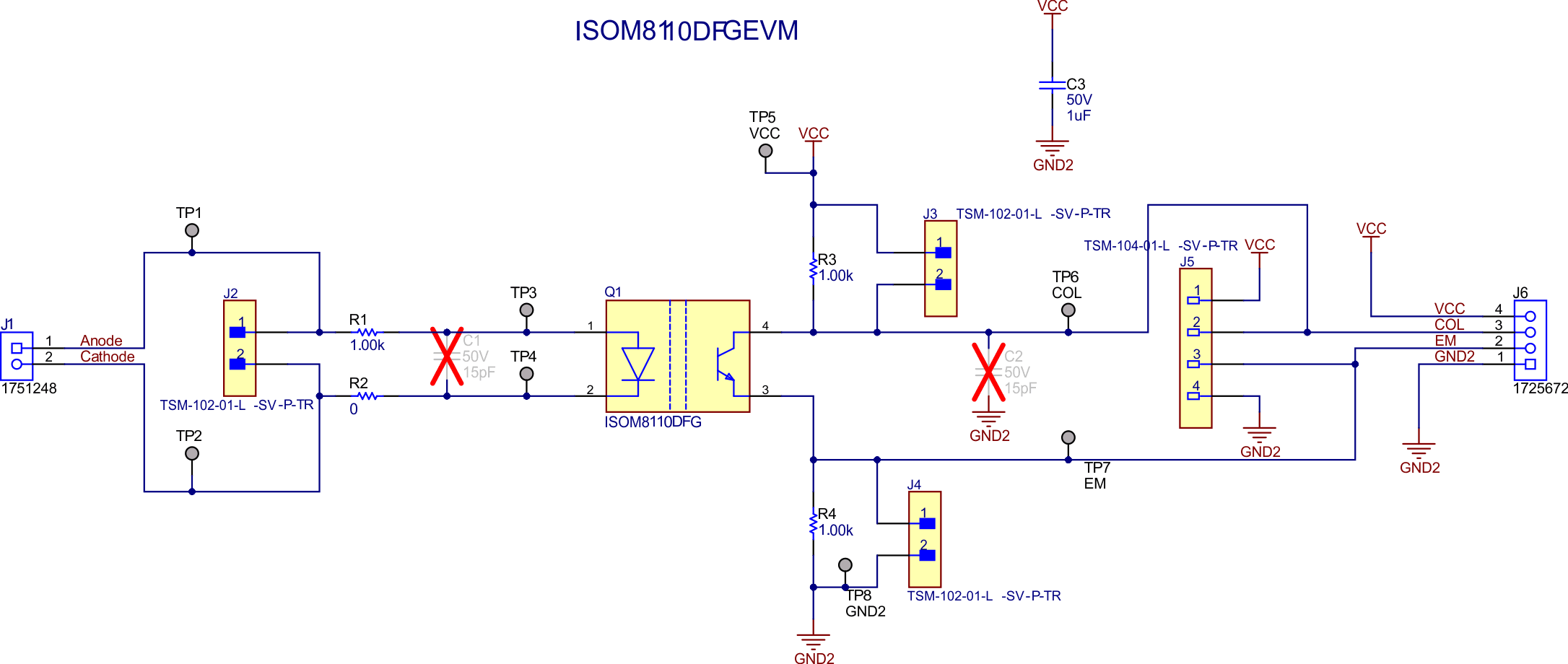
The ISOM8110DFGEVM has additional footprints that gives the user flexibility to test a variety of common applications.
Other positions on the board can be modified as well. For example, R1 can be changed to accommodate different current requirements, and C2 can be added to test the device with resistive or capacitive loading. See ISOM8110DFGEVM for the EVM schematic and see Table 3-1 for more information on alternate EVM configurations.
 Figure 3-1 ISOM8110DFGEVM
Schematic