SLAU915 May   2024 ULC1001


  1.   1
  2.   Description
  3.   Get Started
  4.   Features
  5.   5
  6. 1Evaluation Module Overview
    1. 1.1 Introduction
    2. 1.2 Kit Contents
    3. 1.3 Specification
    4. 1.4 Device Information
    5. 1.5 General Texas Instruments High Voltage Evaluation (TI HV EVM) User Safety Guidelines
  7. 2Hardware
    1. 2.1 Hardware Information
    2. 2.2 Connection Procedure
  8. 3Software
    1. 3.1 GUI Setup
    2. 3.2 System Overview
      1. 3.2.1 System ISR Period
      2. 3.2.2 System Drive Voltage
      3. 3.2.3 System Calibration
        1. 3.2.3.1 DC Bias Calibration
        2. 3.2.3.2 Temperature Calibration
        3. 3.2.3.3 Auto Sense Calibration
        4. 3.2.3.4 Cleaning and Power Calibration
      4. 3.2.4 System Cleaning
      5. 3.2.5 System Diagnostics
    3. 3.3 GUI Overview
      1. 3.3.1 GUI Top Level Layout
        1. 3.3.1.1 North Pane
        2. 3.3.1.2 South Pane
        3. 3.3.1.3 Center Pane
      2. 3.3.2 High Level Page
        1. 3.3.2.1 Burst Parameters
        2. 3.3.2.2 Calibration Settings
          1. 3.3.2.2.1 Voltage and Current Sense Circuitry
        3. 3.3.2.3 Cleaning Mode Settings
          1. 3.3.2.3.1 Auto-Cleaning
          2. 3.3.2.3.2 Water Cleaning
          3. 3.3.2.3.3 Deice Cleaning
          4. 3.3.2.3.4 Mud Cleaning Mode
        4. 3.3.2.4 Power and Diagnostic Settings
      3. 3.3.3 Register Map Page
      4. 3.3.4 I2C Configuration Page
      5. 3.3.5 GUI Functions
        1. 3.3.5.1 Monitor Communication Status
        2. 3.3.5.2 Load and Save Configuration Files
          1. 3.3.5.2.1 MSP430 Firmware Programming
        3. 3.3.5.3 Re-initialize System
        4. 3.3.5.4 Fault and Flag Monitoring and Clearing
        5. 3.3.5.5 Run Calibration
        6. 3.3.5.6 Run Cleaning Modes
        7. 3.3.5.7 Run Diagnostic Mode
        8. 3.3.5.8 Run Abort
        9. 3.3.5.9 Script Recording
  9. 4Hardware Design Files
    1. 4.1 Schematics
    2. 4.2 PCB Layouts
    3. 4.3 Bill of Materials (BOM)
  10. 5Additional Information
    1. 5.1 Trademarks

Register Map Page

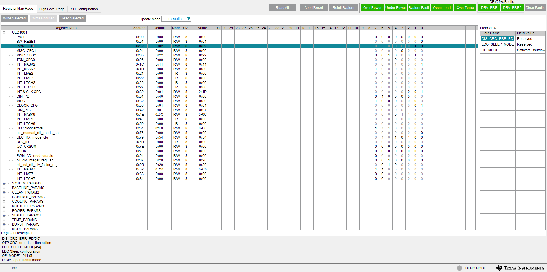
The Register Map Page lists the ULC1001 Registers and the details in a spreadsheet view. Figure 4-19 shows an example of the Hardware Register and Figure 4-20 shows an example of the Firmware Register in the GUI. Clicking on a register shows the different fields on the right. Moving the mouse over a field highlights the corresponding bits in the tree. The value of a register can be set in one of the following three ways:

  1. Double-clicking and entering a hex value in Value column.
  2. Single-clicking on any bit to toggle between 0 and 1.
  3. Changing the field value in the Field View.

The Field Value and Register Value, which is actually set to the device, do not match due to the scale factors that are automatically applied in the GUI back end. Certain Registers are related, such as the registers corresponding to the burst parameters in the high level page. When a Register value is updated in the Register Map Page, the dependent registers, if any, are also updated.
Note: Not all parameter optimization functions, such as value bounding and rounding functions, performed to the high level page fields are performed in the Register Map Page. For any register written in the Register Map Page, these registers do not have the values optimized until the user switches back to the High Level Page.
ULC1001-DRV2911EVM GUI Register Map Page
                    (Hardware Register) Figure 3-19 GUI Register Map Page (Hardware Register)
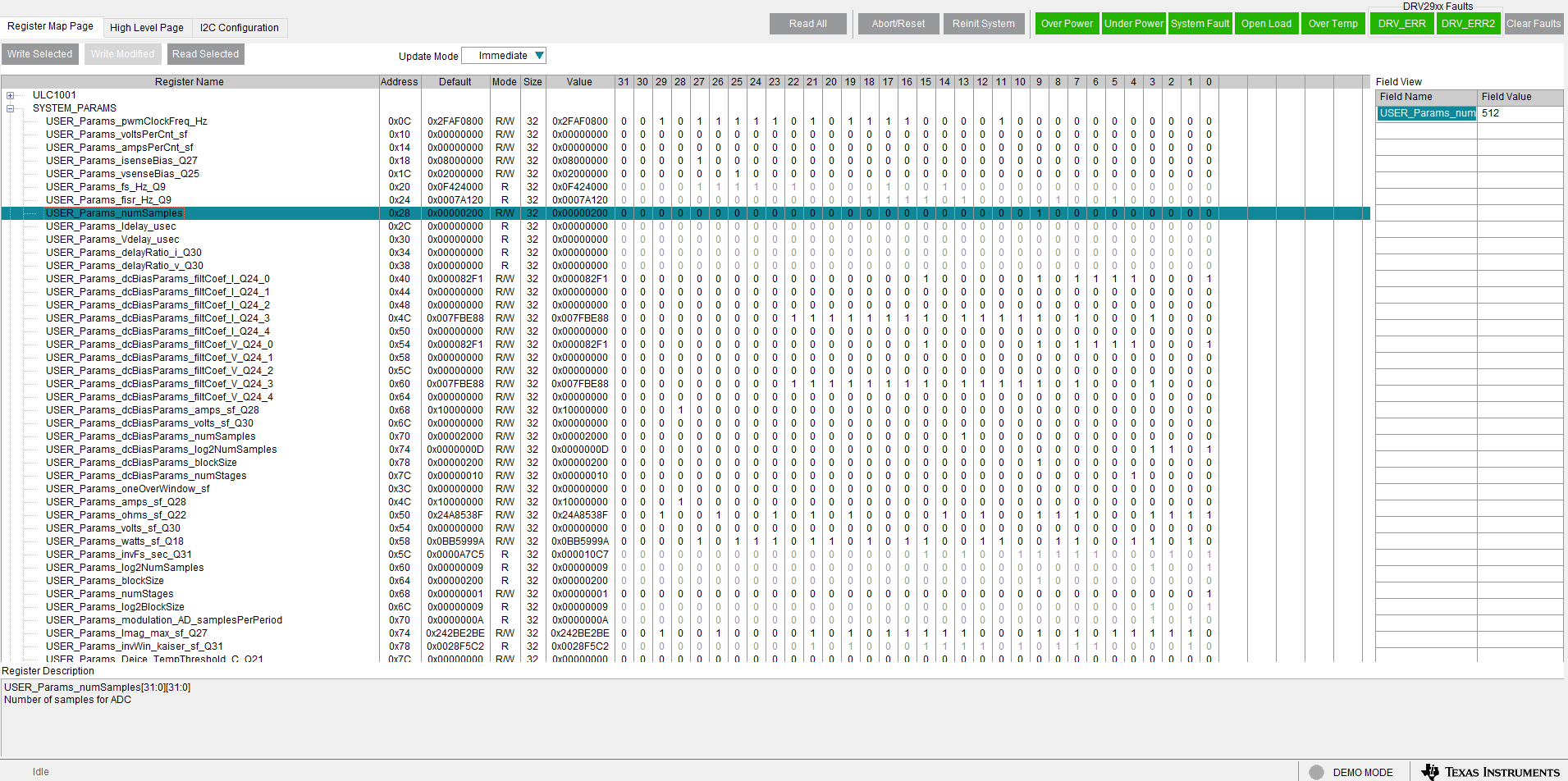
ULC1001-DRV2911EVM GUI Register Map Page
                    (Software Registers) Figure 3-20 GUI Register Map Page (Software Registers)
Note: Register USER_Params_numSamples has no Q-point notation. Whereas register USER_Params_fisr_Hz_Q9 has a Q9 notation. For example, 976.5625 in Q9 notation can be calculated using the formula 976.5625∗2^9 = 500000. Then convert 500000 to binary 32-bit value.