SLAU915 May   2024 ULC1001


  1.   1
  2.   Description
  3.   Get Started
  4.   Features
  5.   5
  6. 1Evaluation Module Overview
    1. 1.1 Introduction
    2. 1.2 Kit Contents
    3. 1.3 Specification
    4. 1.4 Device Information
    5. 1.5 General Texas Instruments High Voltage Evaluation (TI HV EVM) User Safety Guidelines
  7. 2Hardware
    1. 2.1 Hardware Information
    2. 2.2 Connection Procedure
  8. 3Software
    1. 3.1 GUI Setup
    2. 3.2 System Overview
      1. 3.2.1 System ISR Period
      2. 3.2.2 System Drive Voltage
      3. 3.2.3 System Calibration
        1. 3.2.3.1 DC Bias Calibration
        2. 3.2.3.2 Temperature Calibration
        3. 3.2.3.3 Auto Sense Calibration
        4. 3.2.3.4 Cleaning and Power Calibration
      4. 3.2.4 System Cleaning
      5. 3.2.5 System Diagnostics
    3. 3.3 GUI Overview
      1. 3.3.1 GUI Top Level Layout
        1. 3.3.1.1 North Pane
        2. 3.3.1.2 South Pane
        3. 3.3.1.3 Center Pane
      2. 3.3.2 High Level Page
        1. 3.3.2.1 Burst Parameters
        2. 3.3.2.2 Calibration Settings
          1. 3.3.2.2.1 Voltage and Current Sense Circuitry
        3. 3.3.2.3 Cleaning Mode Settings
          1. 3.3.2.3.1 Auto-Cleaning
          2. 3.3.2.3.2 Water Cleaning
          3. 3.3.2.3.3 Deice Cleaning
          4. 3.3.2.3.4 Mud Cleaning Mode
        4. 3.3.2.4 Power and Diagnostic Settings
      3. 3.3.3 Register Map Page
      4. 3.3.4 I2C Configuration Page
      5. 3.3.5 GUI Functions
        1. 3.3.5.1 Monitor Communication Status
        2. 3.3.5.2 Load and Save Configuration Files
          1. 3.3.5.2.1 MSP430 Firmware Programming
        3. 3.3.5.3 Re-initialize System
        4. 3.3.5.4 Fault and Flag Monitoring and Clearing
        5. 3.3.5.5 Run Calibration
        6. 3.3.5.6 Run Cleaning Modes
        7. 3.3.5.7 Run Diagnostic Mode
        8. 3.3.5.8 Run Abort
        9. 3.3.5.9 Script Recording
  9. 4Hardware Design Files
    1. 4.1 Schematics
    2. 4.2 PCB Layouts
    3. 4.3 Bill of Materials (BOM)
  10. 5Additional Information
    1. 5.1 Trademarks

Connection Procedure

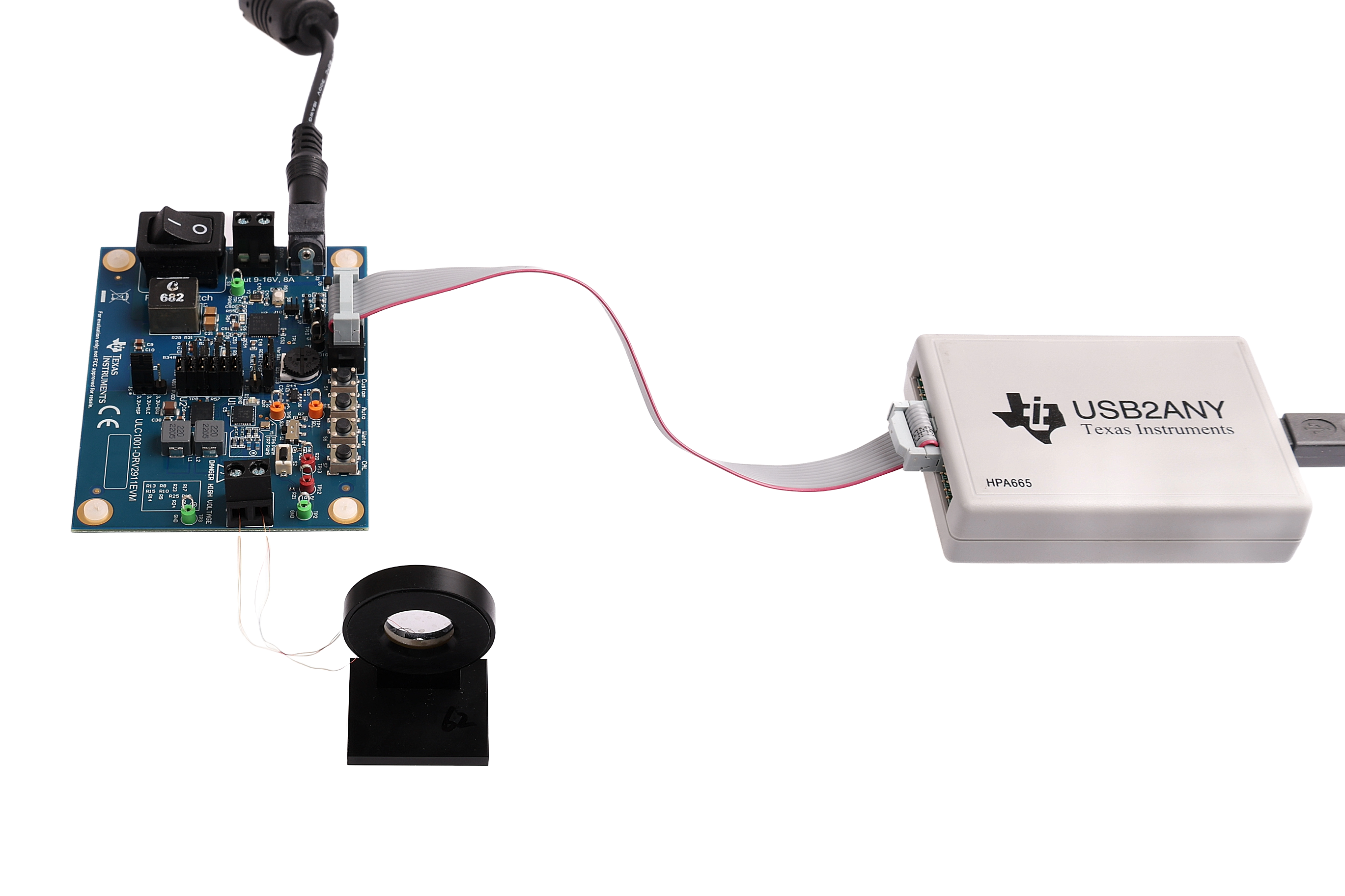
The ULC1001-DRV2911EVM image is shown in ULC1001-DRV2911EVM. The entire EVM, LCS, and USB2ANY setup is shown in Figure 3-1. Follow these instructions to setup the system.

  1. Flip PWR switch off (off = O).
  2. With the power supply unplugged or off, connect to J3 or J4. Input 9-16V, 8A. The 8A current is based on load requirements.
  3. Make sure the LCS or load is discharged and plug the LCS cable into the J2 terminal block. Output, 0-250 Vp, 3.5A, 10-400 kHz.
  4. Connect the 10-pin I2C ribbon cable from the ULC1001-DRV2911 EVM to the USB2ANY using J1.
  5. Connect the mini USB cable from the USB2ANY into the computer.
  6. Verify all safety procedures are followed before powering on the device (for example, personal protective equipment or a protective enclosure for the EVM setup).
  7. Turn on the power supply.
  8. Flip the Power Switch switch to the on position (on = I).
  9. Download and install the ULC1001 GUI available on TI mySecureSoftware.
CAUTION:
ULC1001-DRV2911EVM
Do not leave EVM powered when unattended.

ULC1001-DRV2911EVM EVM System Setup Example
Figure 2-1 EVM System Setup Example