-
MSPM0 Sensored FOC
- 1
- Abstract
- Trademarks
- 1Introduction
-
2Hardware Setup
- 2.1 EVM Hardware Setup
- 2.2 Pin Configurations for PWM Outputs
- 2.3 Pin Configurations for ADC Currents
- 2.4 Pin Configurations for ADC Voltages
- 2.5 Pin Configurations for Hall Sensor Inputs Through GPIO
- 2.6 Pin Configurations for Faults
- 2.7 Pin Configurations for GPIO Output Functions
- 2.8 Pin Configurations for SPI Communication
- 2.9 Pin Configurations for UART Communication
- 2.10 External Connections for Evaluation Boards
- 3Software Setup
- 4GUI Setup
-
5Register Map
- 5.1 Register Map Page in GUI
- 5.2
User Control Registers (Base Address = 0x20200400h)
- 5.2.1 Speed Control Register (Offset = 0h) [Reset = 00000000h]
- 5.2.2 Algo Debug Control 1 Register (Offset = 4h) [Reset = 00000000h]
- 5.2.3 Algo Debug Control 2 Register (Offset = 8h) [Reset = 00000000h]
- 5.2.4 Algo Debug Control 3 Register (Offset = Ch) [Reset = 00000000h]
- 5.2.5 DAC Configuration Register (Offset = 10h) [Reset = 00000000h]
- 5.3
User Input Registers (Base Address = 0x20200000h)
- 5.3.1 SYSTEM_PARAMETERS (Offset = 0h)
- 5.3.2 MOTOR_STARTUP1 Register (Offset = 3Ch) [Reset = 00000000h]
- 5.3.3 MOTOR_STARTUP2 Register (Offset = 40h) [Reset = 00000000h]
- 5.3.4 CLOSED_LOOP1 Register (Offset = 44h) [Reset = 00000000h]
- 5.3.5 CLOSED_LOOP2 Register (Offset = 48h) [Reset = 00000000h]
- 5.3.6 FIELD_CTRL Register (Offset = 4Ch) [Reset = 00000000h]
- 5.3.7 FAULT_CONFIG1 Register (Offset = 50h) [Reset = 00000000h]
- 5.3.8 FAULT_CONFIG2 Register (Offset = 54h) [Reset = 00000000h]
- 5.3.9 MISC_ALGO Register (Offset = 58h) [Reset = 00000000h]
- 5.3.10 PIN_CONFIG Register (Offset = 5Ch) [Reset = 00000000h]
- 5.3.11 PERI_CONFIG Register (Offset = 60h) [Reset = 00000000h]
- 5.4 User Status Registers (Base Address = 0x20200430h)
- 6Basic Tuning
-
7Advanced Tuning
- 7.1
Control Configurations Tuning
- 7.1.1 Control Mode of Operation
- 7.1.2 Stopping Motor Quickly
- 7.1.3 Flux Weakening: Operating Motor at Speeds Higher Than Rated Speed
- 7.1.4 Maximum Torque Per Ampere : Improve Efficiency of IPMSM Motors
- 7.1.5 Preventing Supply Voltage Overshoot During Motor Stop.
- 7.1.6 Protecting the Power Supply
- 7.1.7 FOC Bandwidth Selection
- 7.1
Control Configurations Tuning
- 8Hardware Configurations
- 9Revision History
- IMPORTANT NOTICE
MSPM0 Sensored FOC
Abstract
This tuning guide provides step-by-step guidance to set up an MSPM0 MCU and supported DRV hardware board to tune and spin 3-phase brushless DC motor using Sensored FOC Algorithm.
Trademarks
LaunchPad™ and Code Composer Studio™ are trademarks of Texas Instruments.
Arm® and Cortex® are registered trademarks of Arm Limited.
All trademarks are the property of their respective owners.
1 Introduction
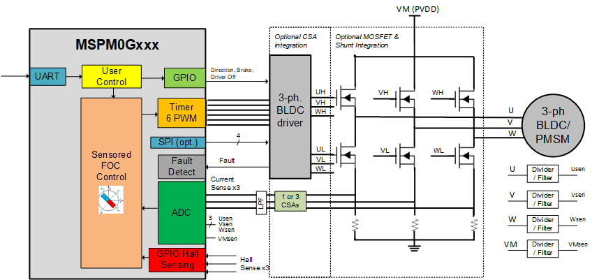
The MSPM0Gxxx family of 80MHz Arm®-Cortex® M0+ MCUs can commutate a Hall Sensor embedded 3-phase brushless DC (BLDC) motor with FOC control. The BLDC motor is driven by a three-phase brushless DC (BLDC) MOSFET gate driver or integrated MOSFET motor driver at 12V or 24V nominal DC rails or battery-powered applications. The driver typically integrates three current-sense amplifiers (CSAs) for sensing the three-phase currents of BLDC motors to achieve optimum FOC control.
Figure 1-1 shows a simplified schematic of an MSPM0Gxxx MCU and BLDC motor driver.
 Figure 1-1 Simplified Schematic of MSPM0Gxxx + BLDC
Motor Driver
Figure 1-1 Simplified Schematic of MSPM0Gxxx + BLDC
Motor DriverThis tuning guide provides the steps to tune a 3-phase BLDC motor using an MSPM0Gxxxx MCU. The tuning process is classified into four sections: Hardware Setup, Software Setup, Basic Tuning and Advanced Tuning.
- Hardware setup: Steps to set up TI-provided hardware or use a custom PCB for the tuning process.
- Software setup: Steps to set up TI-provided software for spinning and tuning a BLDC motor.
- Basic tuning: Tuning steps to successfully spin the motor in closed loop.
- Advanced tuning: Tuning steps to conform to use-case and explore features in the device.
2 Hardware Setup
The following items are required to use this tuning guide:
- LP-MSPM0G3507 board
- Supported DRV83xx motor driver
evaluation module (EVM)
- DRV8316REVM
- Jumper wires for pin table connections
- A computer with the MSPM0 Latest SDK software installed
- A BLDC motor with Hall Sensor to be tuned using this process. The motor data sheet is helpful but not mandatory.
- A DC power supply rated for the motor
- Basic lab equipment such as a digital multimeter (DMM), oscilloscope, current probe, and voltage probe
Figure 2-1 shows the block diagram connections for a Sensored FOC motor system. The system can be built using:
- TI-provided hardware (LP-MSPM0G3507 and DRV83xx EVM)
- Custom PCB hardware with an onboard MSPM0Gxxx MCU and a BLDC motor driver
The following sections describe how to configure the pins for each portion of the Sensored FOC block diagram.
 Figure 2-1 MSPM0Gxxx + BLDC Motor Driver
- Sensored FOC Block Diagram
Figure 2-1 MSPM0Gxxx + BLDC Motor Driver
- Sensored FOC Block DiagramThe System Configuration tool (SysConfig) helps to configure the pins in a motor control system. The default pin configurations are provided for the EVM hardware setup to spin a motor, but pins can be remapped to other pins visually inside SysConfig. This is useful for reconfiguring different pins (such as PWM, ADC, or other control signals) on a custom PCB or for scaling to different packages across MSPM0 devices.
2.1 EVM Hardware Setup
TI provides LaunchPad™ development kits to evaluate MSPM0 Arm Cortex-M0+ microcontrollers and evaluation modules (EVMs) to evaluate the DRV83xx family of brushless-DC motor drivers. These evaluation boards are available on ti.com and can be used as a system evaluation platform for Sensored FOC motor control.
For supported evaluation boards, see Section 2.1.1.