SLIU002A September 2008 – October 2022 TPIC74100-Q1
2.1 Input/Output Connector Description
J1 – VBAT is the power input terminal for the converter. The terminal provides power (Vbat).
J2 – GND is the ground terminal for the EVM.
J3 – 5Vg is the power output terminal for the 5Vg regulator output.
J4 – VOUT is the regulated output voltage for the converter.
J5 – GND is a ground terminal for the EVM.
JP1, JP2 – SCR1, SCR0 are jumpers used to set the slew rate of the switching transistor for the L1 terminal switch pin. Jumpers allow the slew rate to be set to four set points.
 Figure 2-1 Slew Rate Jumper Settings
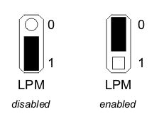
JP3 – LPM is the jumper used to enable Low Power Mode. The jumper allows LPM to be enabled or disabled. The device will operate in Normal mode when LPM is disabled.
 Figure 2-2 Low Power Mode Jumper Settings
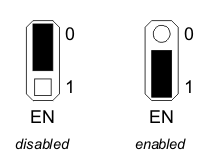
JP4 – Enable is the jumper used to enable the converter. The converter is enabled when the Enable is high and disabled when low. The jumper placement allows the converter to be enabled or disabled.
 Figure 2-3 Enable Jumper Settings
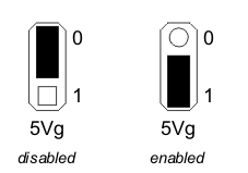
JP5 – 5VgEN is the jumper used to enable switched 5V regulated output. The output is enabled when the Enable is high and disabled when low. The jumper placement allows the converter to be enabled or disabled.
 Figure 2-4 5Vg Regulated Output Jumper Settings
JP6 – Bypass is the jumper used to bypass the low pass filter inductor on the power supply input to the device. This allows the user to remove the filter from the circuit. The jumper placement allows the inductor to be active or shorted.
 Figure 2-5 Low Pass Filter Inductor Bypass Jumper Settings