SLLA272D February 2008 – May 2021
11 Grounding and Isolation
When designing a remote data link, the designer must assume that large ground potential differences (GPD) exist. These voltages add as common-mode noise, Vn, to the transmitter output. Even if the total superimposed signal is within the receiver’s input common-mode range, relying on the local earth ground as a reliable path for the return current is dangerous (see Figure 11-1a).
 Figure 11-1 Design Pitfalls to be Aware off: a)
High GPD, b) High Loop Current, c) Reduced Loop Current, Yet Highly Sensitive to Induced
Noise Due to Large Ground Loop
Figure 11-1 Design Pitfalls to be Aware off: a)
High GPD, b) High Loop Current, c) Reduced Loop Current, Yet Highly Sensitive to Induced
Noise Due to Large Ground LoopBecause remote nodes are likely to draw their power from different sections of the electrical installation, modification to the installation, (i.e., during maintenance work), can increase the GPD to the extent that the receiver’s input common-mode range is exceeded. Thus, a data link working today might cease operation sometime in the future.
The direct connection of remote grounds through ground wire also is not recommended (see Figure 11-1b), as this causes large ground loop currents to couple into the data lines as common-mode noise.
To allow for a direct connection of remote grounds, the RS485 standard recommends the separation of device ground and local system ground via the insertion of resistors (Figure 11-1c). Although this approach reduces loop current, the existence of a large ground loop keeps the data link sensitive to noise generated somewhere else along the loop. Thus, a robust data link has not been established yet.
The approach to tolerate GPDs up to several kilovolts across a robust RS-485 data link and over long distance is the galvanic isolation of the signal and supply lines of a bus transceiver from its local signal and supply sources (see Figure 11-2).
 Figure 11-2 Isolation of Two Remote Transceiver
Stations With Single-Ground Reference
Figure 11-2 Isolation of Two Remote Transceiver
Stations With Single-Ground ReferenceIn this case, supply isolators, such as isolated DC/DC converters, and signal isolators, such as digital, capacitive isolators, prevent current flow between remote system grounds and avoid the creation of current loops.
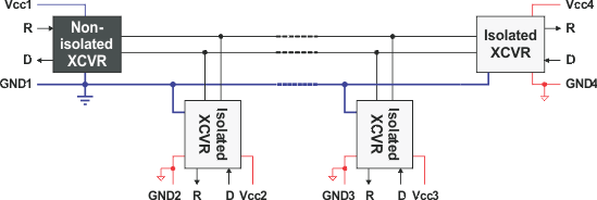
Whereas Figure 11-2 shows the detailed connection of only two transceiver nodes, Figure 11-3 gives an example for multiple, isolated transceivers. All transceivers but one connect to the bus via isolation. The non-isolated transceiver on the left provides the single-ground reference for the entire bus.
 Figure 11-3 Isolation of Multiple Fieldbus
Transceiver Stations