SLLA498A October   2020  – December 2024


  1.   1
  2.   Abstract
  3.   Trademarks
  4. 1Introduction
  5. 2Solar String Inverters
    1. 2.1 Power Stages for DC/DC MPPT
    2. 2.2 Power Stages for Battery Port DC/DC
    3. 2.3 Power Stages for Single-Phase DC/AC
    4. 2.4 Power Stages for Three-Phase DC/AC
  6. 3Future Technology and Trends
  7. 4Summary
  8. 5References
  9. 6Revision History

Power Stages for Three-Phase DC/AC

Three-phase topologies include two-level converter, three-level NPC, and three-level ANPC (TIDA-010210), T-type (TIDA-01606) and Flying cap. For three-phase systems, an elaborate comparison can be found in Comparison of AC/DC Power-Conversion Topologies for Three-Phase Industrial Systems. Table 2-2 lists the benefits and challenges with each of these systems.
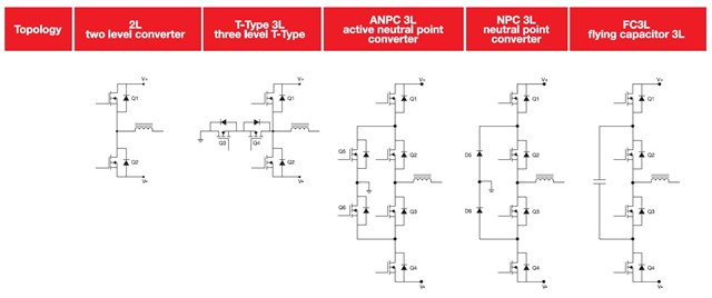
 Schematic Representation of
                Three-phase DC/AC Topologies Figure 2-5 Schematic Representation of Three-phase DC/AC Topologies
Table 2-2 Benefits and Challenges of Three-phase DC/AC Topologies
2L T-Type 3L ANPC NPC 3L Derived From ANPC Flying Capacitor 3L
Benefits
  • Simple control scheme
  • 2 switches only
  • 2 PWM
  • Simple control scheme
  • Q3/Q4 see 1/2 VDC
  • Better EMI than 2L
  • fripple=fpwm
  • Good efficiency
  • All switches see 1/2 VDC
  • Better EMI than 2L
  • Lower cost than ANPC
  • All switches see 1/2 VDC
  • Better EMI than 2L
  • fripple=fpwm
  • 4 PWM
  • Highest efficiency
  • Only 4 HF FETs and 1 cap
  • fripple=2xfpwm
  • Smallest magnetics
  • Lowest EMI
Challenges
  • Q1/Q2 see full VDC
  • High EMI for bigger fpwm
  • Biggest passives
  • Q1/Q2 see full VDC
  • 4 PWM
  • More complex control scheme
  • Shutdown sequencing critical
  • 6 PWM
  • Lower efficiency than ANPC
  • More complex control
  • Shutdown sequencing critical
  • Initial charging of flying capacitor
  • Shutdown sequencing critical