SLLA656 November 2024 TUSB1021-Q1 , TUSB521-Q1
5 TUSB521-Q1 Configuration Example
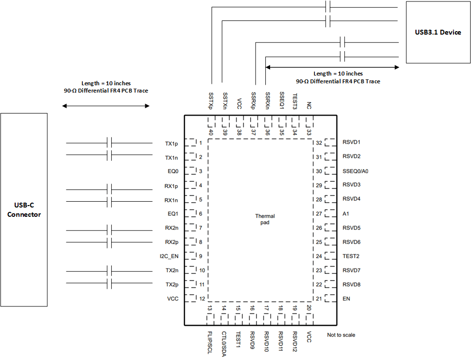
Figure 5-1 provides an example configuration of a device system using a USB3.1 Gen 1 device operating at 5Gbps with the TUSB521-Q1.
 Figure 5-1 TUSB521-Q1 Example
Implementation
Figure 5-1 TUSB521-Q1 Example
ImplementationUsing the given trace lengths in this example, the method to select the equalization values for SSTX and RX1/2 is to select the closest EQ gain available to match the trace loss and additional loss through the connector, components, and device package:
- USB device to TUSB521-Q1 SSTX = 10 inches (-4.9dB) + typical loss in Device package + capacitor (-1.5dB) = total loss of -6.4dB. TUSB521-Q1 SSEQ setting used = Setting #8 (6.4dB).
- Type-C connector to TUSB521-Q1 RX1/RX2 = 5 inches (-2.5dB) + typical connector loss + component (-2dB) = total loss of -4.5dB. TUSB521-Q1 EQ setting used = Setting #4 (4.6dB).
Please note that other factors such as the layout quality, device transmitter and receiver quality require adjusting the EQ settings for best performance. Use the above method to select the initial configuration values based on system board trace lengths.