SLLA656 November 2024 TUSB1021-Q1 , TUSB521-Q1
6.2 AC Coupling and Resistor Placement
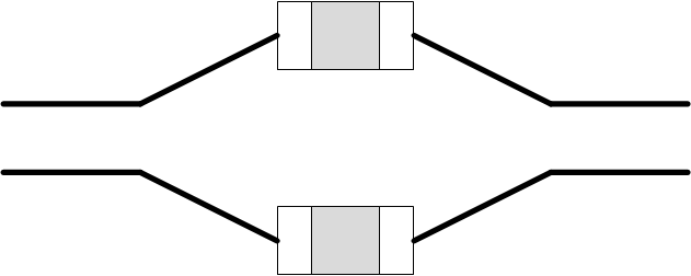
When placing AC-Coupling capacitors, the maximum component size is 0402 . During layout, on the host or device channel, place the AC-Coupling capacitors equidistant to the device and the TUSB521-Q1/TUSB1021-Q1. On the connector to TUSB521-Q1/TUSB1021-Q1 channel, place the AC Coupling caps close to the TUSB521-Q1/TUSB1021-Q1 with symmetrical placement to establish top signal quality and to minimize reflections. Place the optional pull-down resistors so that the pad of the resistor shares the high-speed trace to minimize the presence of a stub. See Figure 6-2 for an example of the optimal AC Coupling capacitor layout symmetry.
 Figure 6-2 AC Coupling Capacitor Layout Example