SLLU359A december 2022 – may 2023
4.4 LED Lights
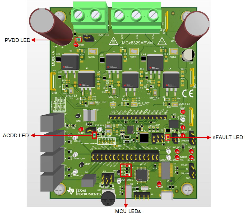
The MCT8329EVM has 5 status LEDs implemented that provide the status of power supplies and functions of the evaluation module. By default, the VM LED and 3.3 V Buck LEDs light up when the board is powered and the program has been flashed onto the microcontroller. Table 4-1 shows LED descriptions including those that are on during power up in bold and Figure 4-5 shows the locations of the LEDs.
Table 4-1 Description of MCT8329EVM LEDs (default in bold after powerup)
| Designator | Name | Color | Description |
|---|---|---|---|
| D1 | AVDD Regulator | Green | Lights up when AVDD is turned ON. |
| D2 | nFAULT | Red | Lights up when fault condition has occurred on MCT8329 |
| D3 | PVDD | Green | Lights up when voltage is applied on PVDD. |
| D13 | MSP_LED1 | Red | Used for UART or debugging |
| D14 | MSP_LED2 | Red | Used for UART or debugging |
 Figure 4-5 MCT8329EVM LEDs