SLLU359A december 2022 – may 2023
3 Quick Start Guide
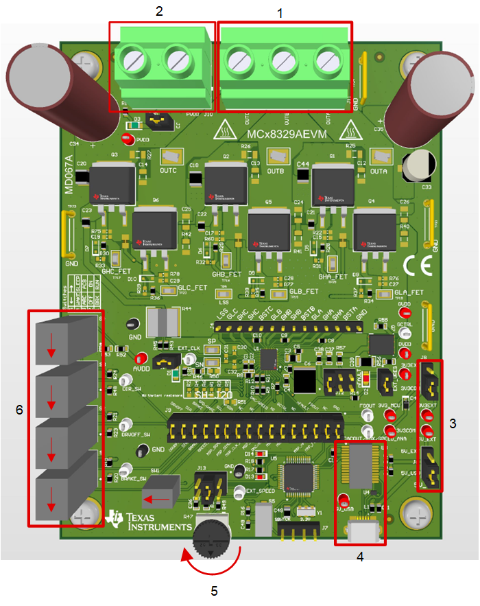
The MCT8329EVM requires a power supply source, which has a recommended operating range from a 4.5-V to 60-V. To setup and power the EVM, follow the sequence below:
- Connect motor phases to A, B, C on connector J11.
- Do not turn on the power supply yet. Connect motor supply to PVDD and GND on connector J10.
- Select J6 to 5V_USB and J8 to 3V3COM to power MSP430 from USB power supply.
- Connect the micro-USB cable into the computer.
- Turn the potentiometer fully clockwise to set the motor to zero speed upon powerup.
- Flip the switch S1 to the top to configure BRAKE = RUN, switch S2 to the top to configure DRVOFF = ON, switch S3 to the bottom to configure DIR = ABC, and switch S4 to the bottom to configure to WAKE.
- Flip the switch SW1 to left to configure SPEED/WAKE pin to SPEED mode and DACOUT/SOx/SPEED_ANA pin to DACOUT mode. Note that flipping the switch SW1 to right configures SPEED/WAKE pin to WAKE mode and DACOUT/SOx/SPEED_ANA pin to SPEED_ANA mode. When SW1 is flipped to right, switch S4 can be used to put the device in SLEEP or WAKE mode and potentiometer R47 can be used to apply analog voltage to the DACOUT/SOx/SPEED_ANA pin.
- Select J12 to leftmost position(closer to C6) to apply AVDD to VREG.
- Select J13 to middle position to apply analog voltage from potentiometer R47 to SPEED/WAKE pin.
- Turn on the motor power supply.
- Use the potentiometer R47 to control the speed of the motor and the switches to disable the motor driver, change the direction, or apply a brake to the motor. Optionally, use the GUI (as shown in Section 6) to monitor real-time speed of the motor, put the MCT8329 into a low-power sleep mode, and read status of the LEDs.
 Figure 3-1 Reference for Quick Start Guide