SLOS358C September 2011 – April 2020 THS4531
PRODUCTION DATA.
- 1 Features
- 2 Applications
- 3 Description
- 4 Revision History
- 5 Packaging and Ordering Information
- 6 Electrical Specifications
- 7 Device Information
- 8 Table of Graphs
- 9 Typical Characteristics: VS = 2.7 V
- 10Typical Characteristics: VS = 5 V
-
11Application Information
- 11.1 Typical Characteristics Test Circuits
- 11.2
Application Circuits
- 11.2.1 Differential Input to Differential Output Amplifier
- 11.2.2 Single-Ended Input to Differential Output Amplifier
- 11.2.3 Differential Input to Single-Ended Output Amplifier
- 11.2.4 Input Common-Mode Voltage Range
- 11.2.5 Setting the Output Common-Mode Voltage
- 11.2.6 Single-Supply Operation
- 11.2.7 Low Power Applications and the Effects of Resistor Values on Bandwidth
- 11.2.8 Driving Capacitive Loads
- 11.2.9 Audio Performance
- 11.2.10 Audio On and Off Pop Performance
- 11.3 Audio ADC Driver Performance: THS4531 AND PCM4204 Combined Performance
- 11.4 SAR ADC Performance
- 11.5 EVM and Layout Recommendations
- 12Device and Documentation Support
- 13Mechanical, Packaging, and Orderable Information
11.3 Audio ADC Driver Performance: THS4531 AND PCM4204 Combined Performance
To show achievable performance with a high performance audio ADC, the THS4531 is tested as the drive amplifier for the PCM4204. The PCM4204 is a high-performance, four-channel analog-to-digital (A/D) converter designed for professional and broadcast audio applications. The PCM4204 architecture utilizes a 1-bit delta-sigma modulator per channel incorporating an advanced dither scheme for improved dynamic performance, and supports PCM output data. The PCM4204 provides flexible serial port interface and many other advanced features. Please refer to its data sheet for more information.
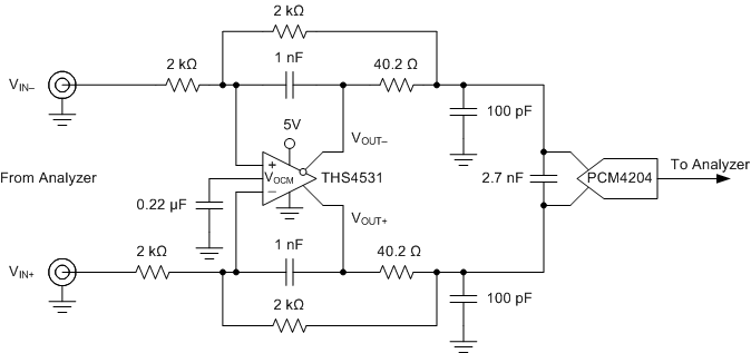
The PCM4204 EVM is used to test the audio performance of the THS4531 as a drive amplifier. The standard PCM4204 EVM is provided with 4x OPA1632 fully differential amplifiers, which use the same pin out as the THS4531. For testing, one of these amplifiers is replaced with a THS4531 device in same package (MSOP), gain changed to 1 V/V, and power supply changed to single supply +5 V. Figure 85 shows the circuit. With single supply +5 V supply the output common-mode of the THS4531 defaults to +2.5 V as required at the input of the PCM4204. So the resistor connecting the VOCM input of the THS4531 to the input common-mode drive from the PCM4204 is optional and no performance change was noted with it connected or removed. The EVM power connections were modified by connecting positive supply inputs, +15 V, +5 VA and +5 VD, to a +5 V external power supply (EXT +3.3 was not used) and connecting -15 V and all ground inputs to ground on the external power supply so only one external +5 V supply was needed to power all devices on the EVM.
 Figure 85. THS4531 and PCM4204 Test Circuit
 An audio analyzer is used to provide an analog audio input to the EVM and the PCM formatted digital output is read by the digital input on the analyzer. Data was taken at fS = 96 kHz, and audio output uses PCM format. Other data rates and formats are expected to show similar performance in line with that shown in the data sheet.
Figure 86 shows the THD+N vs Frequency with no weighting and Figure 87 shows an FFT with 1 kHz input tone. Input signal to the PCM4204 for these tests is -0.5 dBFS. Table 5 summarizes results of testing using the THS4531 + PCM4204 versus typical Data Sheet performance, and show it make an excellent drive amplifier for this ADC.
 Figure 86. THS4531 + PCM4204 THD+N vs Frequency with No Weighting
  Figure 87. THS4531 + PCM4204 1 kHz FFT
 Table 5. 1 kHz AC Analysis: Test Circuit versus PCM4204 Data Sheet Typical Specifications (fS = 96 kSPS)
| CONFIGURATION | TONE | THD + N |
|---|---|---|
| THS4531 + PCM4204 | 1 kHz | -106 dB |
| PCM4204 data sheet (typical) | 1 kHz | -103 dB |