SLOU560 July 2022 TAS2781
4.4 Direct I2C
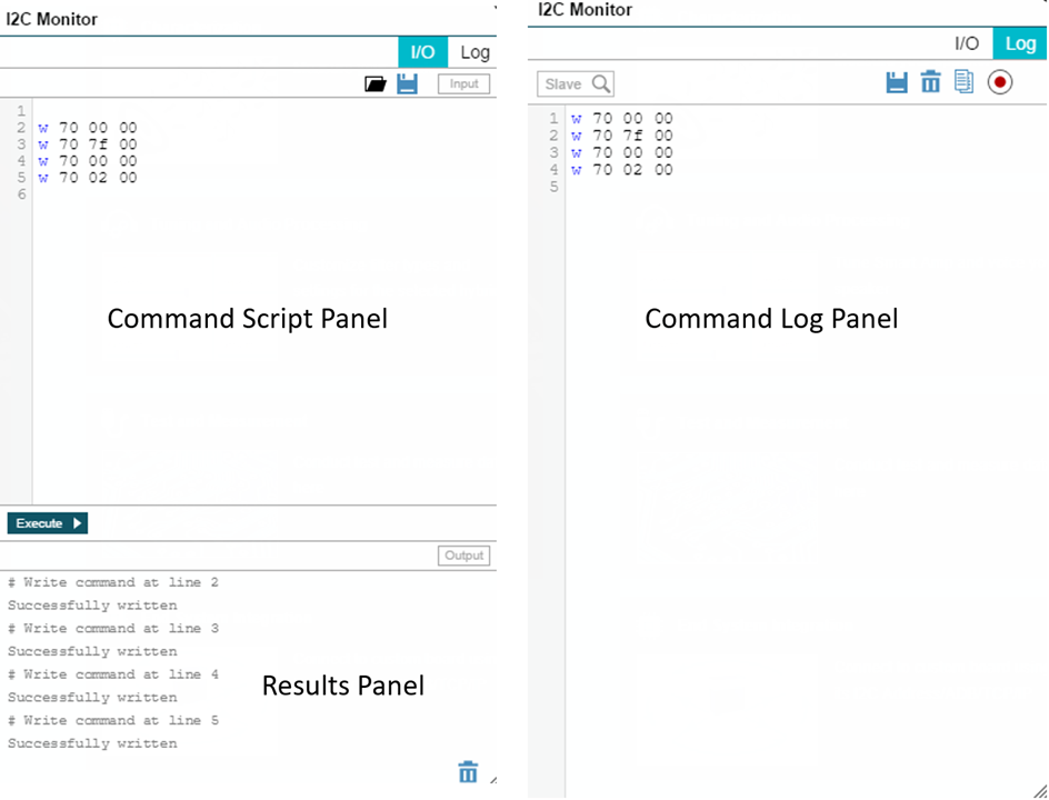
There is a dedicated Direct I2C panel available which offers means to control the device on the evaluation board using configuration scripts in cfg format instead of GUI settings. The same panel also features a Log mode that can be used to record I2C transactions which is useful while debugging.
However the same panel is available in a pop up widow that can be used in any other panel by clicking the button in the bottom center of the PPC3 main window.
 Figure 4-4 PPC3 - I2C Monitor