SLOU571 June 2024
- 1
- Description
- Get Started
- Features
- Applications
- 6
- 1Evaluation Module Overview
- 2Hardware
- 3Hardware Design Files
- 4Additional Information
2.1.1 Jumpers
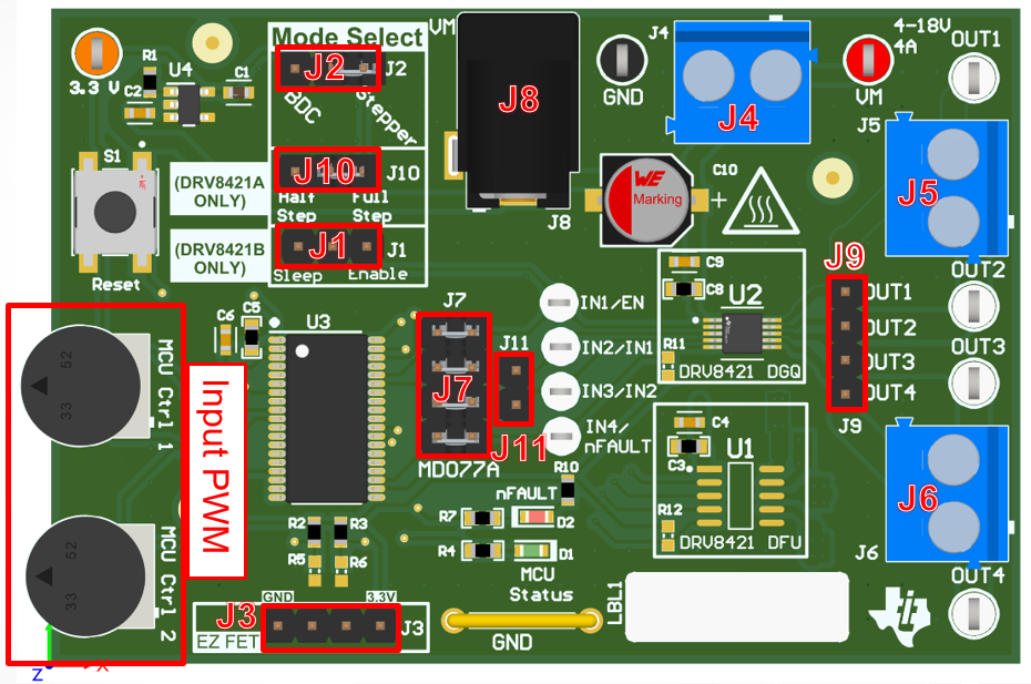
- Please refer to the following figure and table for the location and description of components and jumpers on the board. These jumpers are used to configure the pins on the MSP430 to support various load configurations and board variants.
 Figure 2-1 Jumper Population
Guide
Figure 2-1 Jumper Population
GuideTable 2-1 Jumper Identification
| JUMPERS | DRV8421A | DRV8421B | DESCRIPTION |
|---|---|---|---|
| J1 | Not populated | Sleep/enable jumper | Select low-power sleep mode or enable |
| J2 | Mode select jumper | Mode select jumper | Select Brushed-DC or Stepper Motor |
| J3 | EZ-FET | EZ-FET | Used for programming the MCU |
| J4 | Main power supply terminal | Main power supply terminal | Supplies power to the EVM (only one power supply needed) |
| J5-J6 | Main output terminals |
Main output terminals |
Output terminals for load connections |
| J7 | MCU to DRV8421 | MCU to DRV8421 | Must be populated if using onboard MCU |
| J8 | DC power jack | DC power jack | Alternate power supply connection (only one power supply needed) |
| J9 | Output pins | Output pins | Alternate output pins for connection convenience |
| J10 | Step select jumper | Not populated | Select Full-Step or Half-Step when in Stepper Mode |
| J11 | Parallel mode jumper | Parallel mode jumper | Remove shunt 3 from J7 to use to populate J11 (See Section 2.1.7 for more details) |
For more detailed information, download the hardware files and schematics. Once users have verified that all shunts and jumpers are in the correct location, users can move on to the EVM setup.