SLOU571 June   2024


  1.   1
  2.   Description
  3.   Get Started
  4.   Features
  5.   Applications
  6.   6
  7. 1Evaluation Module Overview
    1. 1.1 Introduction
    2. 1.2 Kit Contents
    3. 1.3 Specification
    4. 1.4 Device Information
  8. 2Hardware
    1. 2.1 EVM Setup and Mode Select
      1. 2.1.1 Jumpers
      2. 2.1.2 DRV8421A: Brushed-DC Setup
      3. 2.1.3 DRV8421A: Stepper Setup
      4. 2.1.4 DRV8421B: Brushed-DC Setup
      5. 2.1.5 DRV8421B: Stepper Setup
      6. 2.1.6 EVM Control
        1. 2.1.6.1 DRV8421A: Brushed-DC Motor Control
        2. 2.1.6.2 DRV8421A: Stepper Motor Control
        3. 2.1.6.3 DRV8421B: Brushed-DC Motor Control
        4. 2.1.6.4 DRV8421B: Stepper Motor Control
      7. 2.1.7 Parallel Mode
        1. 2.1.7.1 DRV8421A: Parallel Mode
        2. 2.1.7.2 DRV8421B: Parallel Mode
      8. 2.1.8 Removing and Installing Supported Motor Drivers
  9. 3Hardware Design Files
    1. 3.1 Schematics
    2. 3.2 PCB (Top-Assembly View)
    3. 3.3 Bill of Materials (BOM)
  10. 4Additional Information
    1. 4.1 Trademarks

DRV8421B: Stepper Setup

The following configuration must be used when driving a stepper motor and the DRV8421B variant is populated on the EVM.

  • J2: Populated for stepper motor mode
  • J10: Remove Step Select Jumper (DRV8421B is automatically configured for Full-Step when (J2) is populated in stepper mode)
  • J1: Select Enable or Sleep configuration (Blue: Enables device, Red: Low-power sleep mode)
  • J7: All populated for MCU communication with DRV8421
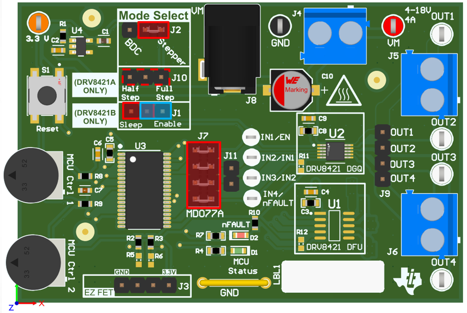
DRV8421AEVM, DRV8421BEVM Jumper Configuration for
                    Stepper Motor Control with DRV8421B Figure 2-5 Jumper Configuration for Stepper Motor Control with DRV8421B