SLUAA12 March 2020 TPS53681
- Selection Considerations for Output Capacitors of Multiphase Voltage Regulators Part 1
2 Current Transfer Function Gii_CL(s) of Load Current to Inductor Current
From Figure 1, the summation of all inductor current is called Isum, undershoot and overshoot occur when Isum cannot track Io quickly. To calculate undershoot and overshoot without DCLL, based on unbalanced electric discharges and charges of output capacitors, the relationship of Isum and Io needs to be clarified. Thus, it's important to know how inductor current IL(Isum in multiphase application) responds when load current Io varies rapidly.
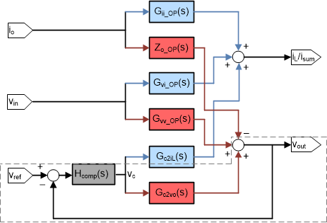
Based on small-signal model of a multiphase buck converter, and the D-CAP+ control modeling, we can derive small-signal transfer functions both in open loop and closed loop, of any input to any output within the system, shown in Figure 3.
All open-loop small-signal transfer functions based on D-CAP+ control mode are listed below:
Table 1. Open-loop Small-signal Transfer Functions in D-CAP+ Control Mode
| Transfer Functions | Explanations |
|---|---|
| Gii_OP(s) | From input Io to output IL/Isum |
| Zo_OP(s) | From input Io to output vout |
| Gvi_OP(s) | From input vin to output IL/Isum |
| Gvv_OP(s) | From input vin to output vout |
| Gc2iL(s) | From input vc to output IL/Isum |
| Gc2vo(s) | From input vc to output vout |
| Hcomp(s) | Loop compensation |
For example, from input Io to output vout, the transfer function is named Zo_OP(s), representing how Io variation affects vout in open loop, also called open-loop output impendence from physical meaning.
Inside the dot line at bottom below, is the common closed-loop control loop called loop gain L(s)=Hcomp(s)*Gc2vo(s). All closed-loop transfer functions can be calculated based on open-loop transfer functions and loop gain together, with signal-flow diagram transformation in Figure 3.
 Figure 3. Signal-Flow Diagram of Small-Signal Model of D-CAP+ Control
 Load current Io to inductor current IL (Isum in multiphase application), as current transfer functions, are our interests here. For clarity, we define symbols as below:
- Gii_OP(s) is open-loop transfer function of Io to Isum
- Gii_CL(s) is closed-loop transfer function of Io to Isum
They describe how Io will affect Isum with specific expression, under open-loop and D-CAP+ closed-loop control in frequency domain.
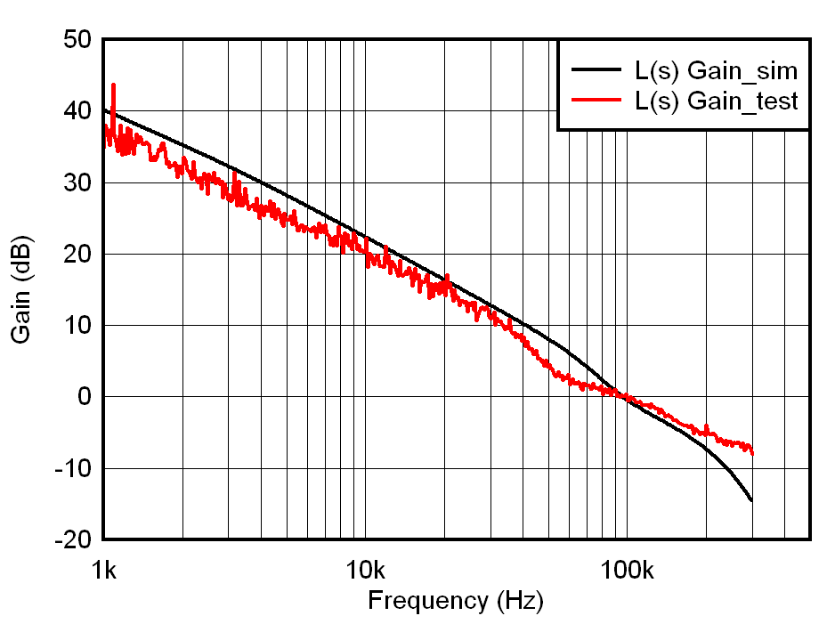
Taking parameters in Table 5 as an example, the bode plot of loop gin L(s) is shown in Figure 4 with results of both simulation and bench test. We can find these two match well with cross frequency fc=~100kHz.
 Figure 4. Bode Plot of Loop Gain L(s) in Simulation and Bench Test
 The good matching result can direct us to extend the usage of simulation tool to estimate other transfer functions. By performing signal-flow diagram transformation in Figure 3, we get the closed-loop equation of Gii_CL(s):

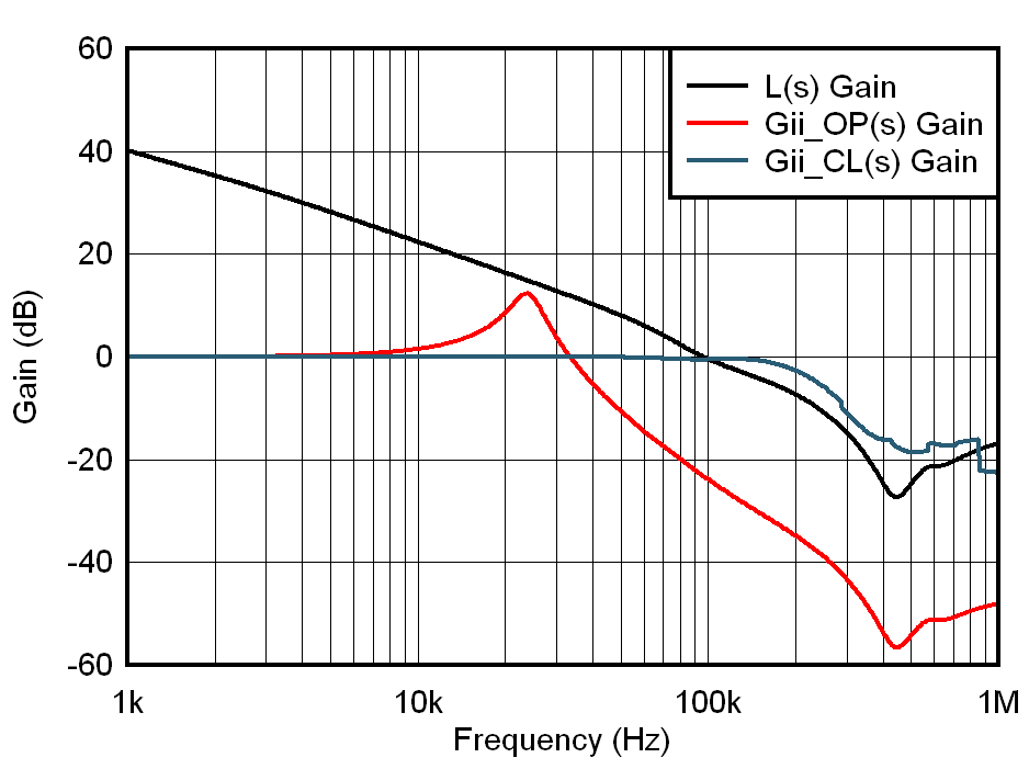
In Figure 5, simulation shows what Gii_CL(s) looks like, when compared with Gii_OP(s) and L(s) together.
 Figure 5. Bode Plot of Gii_CL(s), Gii_OP(s) and L(s) in Simulation
 In conclusion, by D-CAP+ closed-loop control, we can strongly increase the bandwidth of the Gii_OP(s) to much higher, and improve dynamic response of Isum, ensuring itself to follow Io load step as quick as possible. From Figure 5, we can approximately take Gii_CL(s) as a first-order system with corner frequency fci=1.5fc=~150kHz.
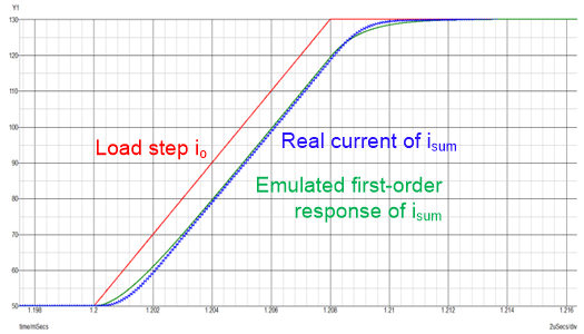
Figure 6 is one simulated example showing that real response of Isum, matches very well with emulated response of the approximate first-order system, under a given ramp-step input.
 Figure 6. Response of Approximate First-Order System
 We will use the response of this approximate Gii_CL(s) to emulate real response of Isum, under a given ramp-step load step, in a linear system without saturation.