SLUAAY1 October 2024 UCC28064A
- 1
- Abstract
- Trademarks
- 1Introduction
- 2Interleaving PFC Principle of Operation
- 3Original PFC Design with Internal Line Feed-Forward block
- 4Current Phenomenon of Operating With UCC28064A Internal Line Feed Forward Function
- 5Achieving Adaptive Current Control PFC With UCC28064A
- 6Test Results Comparing Original PFC Design to Adaptive PFC Design
- 7Summary
- 8References
5 Achieving Adaptive Current Control PFC With UCC28064A
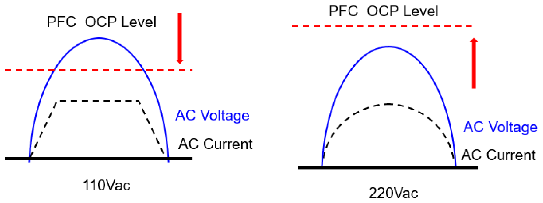
To implement it under AC low-line voltage and full-load, which are the conditions necessary to implement adaptive PFC performance, the apparent OCP level must be reduced. First, at low-line and max-load, set the apparent OCP level to limit peak current so that normal Vout cannot be maintained. Vout below the regulation set-point can drive VCOMP to maximum on-time but OCP level can prevent Vout regulation. When Vout falls to a target threshold (353V in this example) a comparator changes the apparent OCP level even lower and the OCP condition is locked in until either load is lighter or Vin rises.
Afterward, contrary to constant on-time control, when the switching frequency is lowered the current flows to the OCP level over the entire line cycle and the inductor current waveform changes from a sine wave envelope to a trapezoidal envelope.
 Figure 5-1 Concept to Achieving Adaptive PFC Design With OCP Level
Configure the adaptive current limit external circuit as shown in Figure 5-2 to adjust the current limit level according to the PFC output voltage.
The following list details the operating mechanism for external circuit with UCC28064A.
Using the CS pin parameter of UCC28064A, adjust the CS voltage level from -0.2V to -0.162V, limit the output power during OCP operation. For this purpose, the external circuit was configured as follows.
- R6 and R7 set a reference voltage of 12V to the comparator (-) input. R8 and R9 form a divider to set the VPFCOUT threshold to approximately 353V.
- At higher input voltages or lower loads, the PFC output voltage can be regulated and the comparator output is high, keeping Q1 on
- When Q1 is on, R5 is grounded and R2 and R4 form a 3kR/4kR divider across Rsense which reduces the current-sense voltage applied to the CS input by ¾. Internal CS threshold of -0.2V does not change so Rsense peak voltage must exceed -0.267V to trigger OCP
- At low-line and max load, Rsense value is chosen so that the peak voltage triggers OCP and the peak inductor current is not high enough to sustain regulation. When VPFCOUT falls below the 353V threshold, the comparator output goes low and turns Q1 off.
- When Q1 is off, R5 is applied in series with R4 and the R2 and (R4+R5) divider forms 13kR/14kR divider across Rsense which reduces the current-sense voltage applied to the CS input by 13/14. Internal CS threshold of -0.2V does not change so Rsense peak voltage must exceed -0.215V to trigger OCP. This is a change of 0.215/0.267 = 0.808, which effectively changes the internal -0.2V OCP threshold to -0.162V. This becomes an effective hysteresis to reduce inductor peak current even more to make sure that VPFCOUT stays below 353V.
- When input voltage rises or load reduces, the OCP-limited current can allow VPFCOUT to rise above 353V and the comparator drive Q1 on again and the apparent OCP limit is raised back to normal.
- R1 and C1 are for noise filtering only and do not affect the OCP thresholds. No one knows what the purpose of R3 is, but the value is high enough that the value does not affect the OCP thresholds.
 Figure 5-2 External Circuit for Adaptive Current Limit With UCC28064A