SLUUCS6A february 2023 – august 2023 UCC14340-Q1 , UCC14341-Q1
5.9.1 Output UVLO
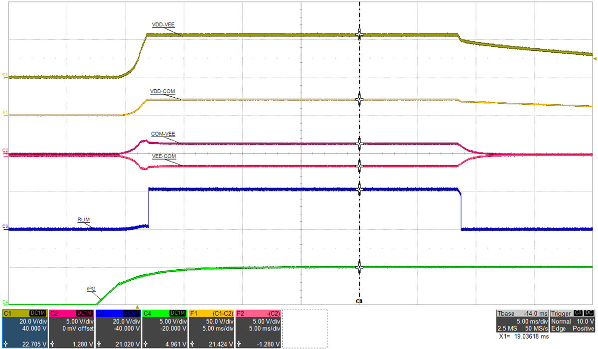
Figure 5-22 shows the effect of mismatched bias loading at startup where the load on VEE-COM is greater than the load on VDD-COM. A fixed resistive overload of 33-Ω (50 mW @ VEE-COM=1.28 V) is applied to VEE-COM while VDD-COM is left unloaded. VDD-VEE is regulating at 22.7-V, as expected but VDD-COM is measuring 21.4 V (18-V setpoint) and VEE-COM is measuring 1.28 V (4-V setpoint). Since VDD-COM is not directly monitored by feedback, over-voltage protection (OVP) is not triggered even though the measured voltage is 18% above the target value. Also, since VEE-COM is overloaded, the regulated voltage is only reaching 1.28 V which is 68% below the targeted set value of 4 V, therefore, VEE-COM UVLO is triggered. RLIM is internally switched to VDD (22 V) and is attempting to overcome the imbalance by sourcing current into the capacitor midpoint, COM connection. FBVDD and FBVEE must both be between 90%-110% of their target set value before 28.4 ms soft-start time as defined by the internal watch-dog-timer. The 28.4-ms, watch-dog-timer UVLO fault protection is enabled to protect the UCC14341-Q1 from output short-circuit or soft overload conditions. When activated, as illustrated in Figure 5-22, the outputs are latched off into a protected sate. EN or VIN must be recycled to clear the UVLO fault and attempt to restart the module. The slow /PG signal rise time is a result of turning on the external EN (and /PG) power supply to turn on/off the EVM.

Figure 5-21 Output UVLO: Vin=15 V, PVDD=0 mW, PVEE=50 mW, (top: VDD-VEE, 20 V/div, mid-1: VDD-COM, 50 V/div, mid-2: COM-VEE, 5 V/div, mid-3: VEE-COM, 5 V/div, mid-4: RLIM, 20 V/div, bot: /PG, 5 V/div), time = 5 ms/div