SLUUCT9 September 2023
3.1 Evaluation Setup
This section describes the default EVM configurations and recommended test set up for the UCC21551-Q1 EVM.
Equipment
The following equipment is recommended for testing the EVM:
- One DC supply capable of 5 V/0.5A, for example: Keysight E3634A.
- One DC supply capable of 24 V/0.5A, for example: Keysight E3634A.
- One Arbitrary Function Generator, dual channel, for example: Tektronix AFG3102A
- One Oscilloscope, at least 3 channels, bandwidth 200 MHz or above, for example, Tektronix MDO3054 or TDS3054C.
- Three passive oscilloscope probes, bandwidth 200 MHz or above. For example, TPP1000 like probe with a ground spring.
- 4X BNC to Grabber Cables for input and supply connections.
- Banana plug connector.
Equipment Configurations
- DC Power Supply Settings
- DC Supply 1:
- Voltage setting: 5 V
- Current limit: 0.5A
- DC Supply 2:
- Voltage setting: 24 V
- Current limit: 0.5A
- DC Supply 1:
- Function Generator Settings
- Function: Pulse
- CH1: High: 5 V, Low: 0 V
- CH2: High: 5 V, Low: 0 V
- Oscilloscope Settings
- CH1-CH3:
- DC coupling
- Highest bandwidth setting available
- Termination 1M or automatic
- Probe scale: 10X or auto
- CH1-CH3:
Equipment Setup
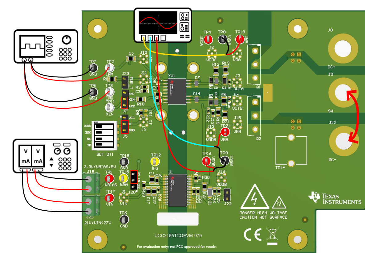
- Jumper Connections
- J7: Shunt XEN to VCC
- J20: Shunt ON to EN
- J5: Shunt DT to GND
- SDT_DT1: All switches in the left most position
- Oscilloscope Connections
- CH1: VGA to VSSA
- CH2: VGB to VSSB
- CH3: VDDB to VSSB
- Function Generator
- CH1: INB to GND
- CH2: INA to GND
- Power Supply
- DC Supply 1: J18
- DC Supply 2: J21
If testing the EVM with FETs, then populate Q1 and Q2 or the XM3 connector. If testing the EVM without FETs, then place a banana plug connector between SW and DC-. See Figure 4-1 for a visual of the default test connections.
 Figure 3-1 Default Connections Without
Load