SLUUCU3
November 2023
1
Description
Get Started
Features
Applications
6
1
Evaluation Module Overview
1.1
Introduction
1.1.1
Before You Begin
1.2
Kit Contents
1.3
Specifications
1.4
Device Information
2
Hardware
2.1
Test Equipment
2.1.1
Voltage Source
2.1.2
Oscilloscope
2.1.3
Multimeters
2.1.4
Output Load
2.1.5
Fan
2.1.6
USB-to-GPIO Interface Adapter
2.1.7
Recommended Wire Gauge
2.1.8
List of Test Points, Jumpers, and Connectors
2.2
Test Setup
2.2.1
Test and Configuration Software
2.2.1.1
Description
2.2.1.2
Features
2.2.2
Evaluating Split Rail Input
3
Software
3.1
Using the Fusion GUI
3.1.1
Opening the Fusion GUI
3.1.2
General Settings
3.1.3
Changing ON_OFF_CONFIG
3.1.4
Pop-Up for Some Commands While Conversion is Enabled
3.1.5
SMBALERT# Mask
3.1.6
Device Info
3.1.7
Phase Commands
3.1.8
All Config
3.1.9
Monitor
3.1.10
Status
3.2
EVM Configuration Using the Fusion GUI
3.2.1
Configuration Procedure
4
Implementation Results
4.1
Performance Data and Typical Characteristic Curves
4.1.1
Efficiency
4.1.2
Load Regulation
4.1.3
Line Regulation
4.1.4
Transient Response
4.1.5
Control Loop Bode Plot
4.1.6
Output Ripple
4.1.7
Control On
4.1.8
Control Off
4.1.9
Thermal Image
4.2
Test Procedure
4.2.1
Line and Load Regulation and Efficiency Measurement Procedure
4.2.2
Efficiency Measurement Test Points
4.2.3
Control Loop Gain and Phase Measurement Procedure
5
Hardware Design Files
5.1
Schematic
5.2
EVM Assembly Drawing and PCB Layout
5.3
Bill of Materials
6
Additional Information
Trademarks
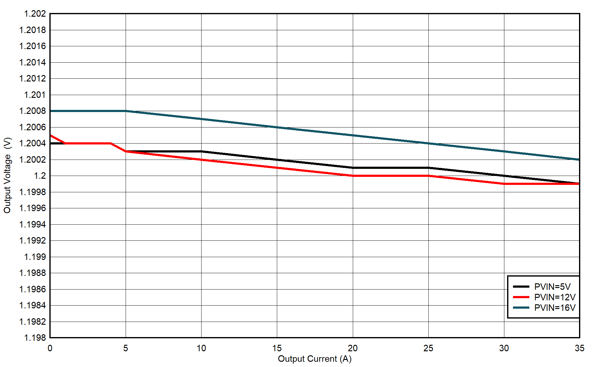
4.1.2
Load Regulation
Figure 4-2
VOUT Load Regulation