SLUUCU8 july 2023
3.1.3 Output Hot-Short Test
Use the following instructions to perform output the hot-short test.
- To avoid drop in input voltage due to the input impedance, additional capacitance can be added across VIN to GND.
- During output short circuit event, when the HGATE turns OFF there can be oscillations on the input voltage due to sudden interruption of current. R13 can be increased to 10 Ω. This 10 Ω resistor along with C8 helps the device from resetting (due to V(VS_PORF)) after HGATE turns OFF.
- Set the input supply voltage VIN to 12 V and current limit of 10 A.
- Turn ON the power supply and observe start-up of output voltage, HGATE, and DGATE.
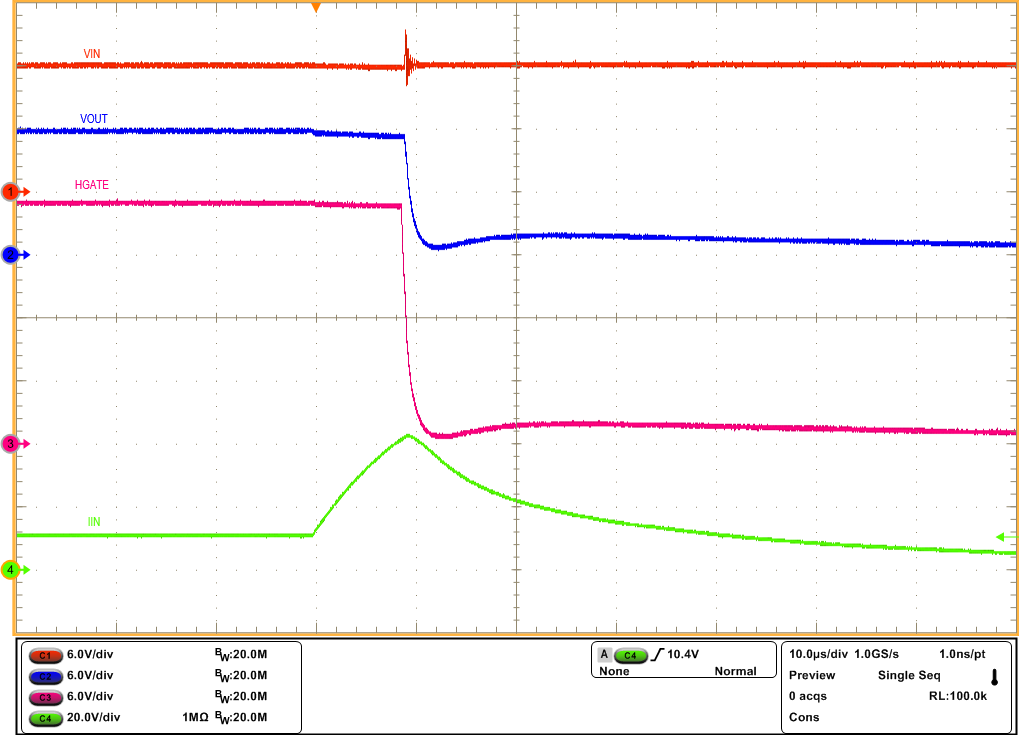
- Short the output to GND. That is, VOUT to GND with a cable and observe the short-circuit response of LM74912-Q1 using an oscilloscope.
Figure 4-7 shows hot-short response of LM74912-Q1 on LM74912Q1EVM evaluation board.
 Figure 3-7 Output Hot-Short Response of
LM74912-Q1 Device