SLVAF16A March 2021 – December 2021 AFE7920 , AFE7950 , TPS541620 , TPS62912 , TPS62913
1.2 Block Diagram
The original AFE7920 RevC evaluation module used a DC-DC converter with LDO followers to provide power to the AFE 1.8 V rails.
 Figure 1-2 Original Power
Block Diagram for AFE7920 RevC Evaluation Module
Figure 1-2 Original Power
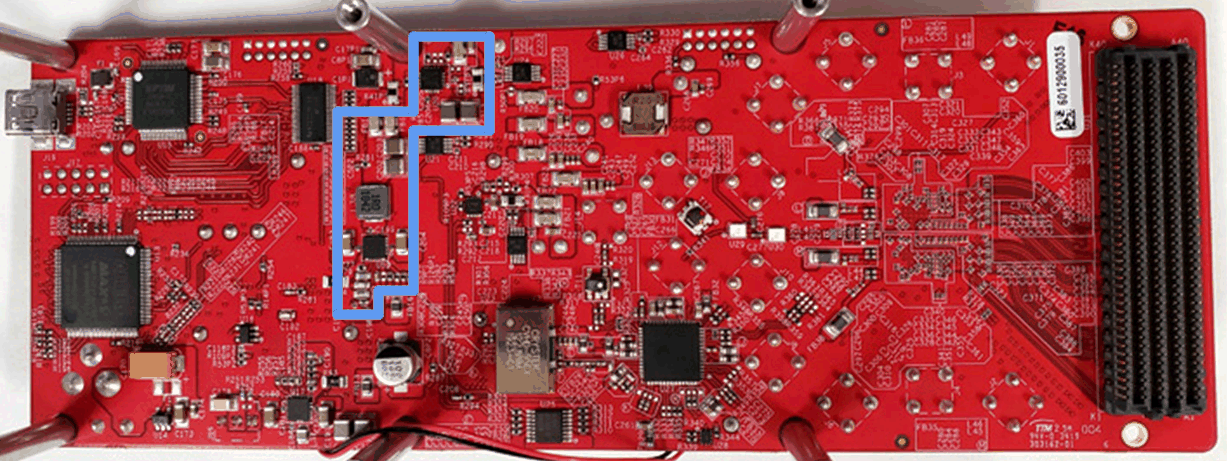
Block Diagram for AFE7920 RevC Evaluation ModuleThe original EVM power supply is outlined in blue and shown in Figure 1-3. The DC/DC and LDO's consume a large amount of the board area in this design, and uses two sides of the board.
 Figure 1-3 Image of top
of Original board with Switchers and LDO's outlined in
Blue
 Figure 1-4 Image of
bottom of Original board with Switchers and LDO's outlined
in Blue
Figure 1-4 Image of
bottom of Original board with Switchers and LDO's outlined
in BlueIn the revised design, the LDOs are removed for the 1.8 V rails, and the TPS62913 low-ripple, low-noise DC-DC converter is used instead. This implementation improves the efficiency (reducing power loss), reduces temp rise, and reduces the part count in comparison to a solution using LDOs while maintaining the output voltage ripple and noise requirements of the AFE for good performance.
 Figure 1-5 Power Block
Diagram for AFE7920 Rev C Evaluation Module with
TPS62913
Figure 1-5 Power Block
Diagram for AFE7920 Rev C Evaluation Module with
TPS62913The updated EVM power supply with the TPS62913 and dual output TPS541620 is outlined in blue and shown in Figure 1-7. The DC/DC solution size is considerably smaller in this design, and is on a single side of the board.
 Figure 1-7 Image of
bottom of Revised board
 The schematics for the 1.8 V rails can be found in the Section 3.
| Component | Original Rev C | Rev C with TPS62913 |
|---|---|---|
| Switching Power Supplies | 1 x TPS54824 (3.5mm x 3.5mm) | 2 x TPS62913 (2mm x 2mm ea) |
| LDO's | 1 x TPS7A85A 4A LDO (3.5mm x 3.5mm), 1 x TPS7A83A 2A LDO (3.5mm x 3.5mm), 1x TPS7A92 1A LDO (2.5mm x 2.5mm) | None |
| Size of Power Supplies | 43 sqmm + passives | 8 sqmm + passives |