SLVAF84 September 2021 DRV8311 , DRV8312 , DRV8313 , DRV8316 , DRV8332 , MCT8316Z
2.4 INHx Falling, INLx Rising, Current is Going Into the Phase
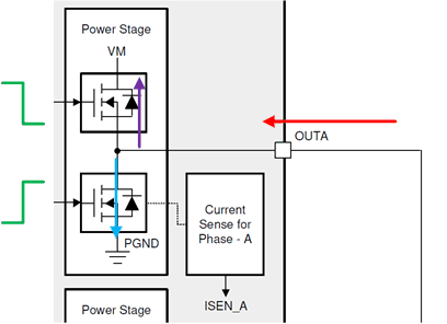
In Figure 2-9, when INHx goes low (green), current is momentarily pulled through the body diode (purple) of the HS FET to continue sinking current into OUTx (red). The duration the body diode of the HS FET conducts is the dead time. When the body diode stops conducting (dead time is over), the LS FET begins to conduct (blue).
 Figure 2-9 Current Switching With INHx Falling, INLx Rising, and Current Into OUTx
Note how the current direction is opposite internally between the body diode of the HS FET and the conduction path of the LS FET. To reduce a large change of current, the device waits until the HS body diode fully conducts and then turns on the LS FET, which lengthens propagation delay to the typical or maximum value as specified in the data sheet.
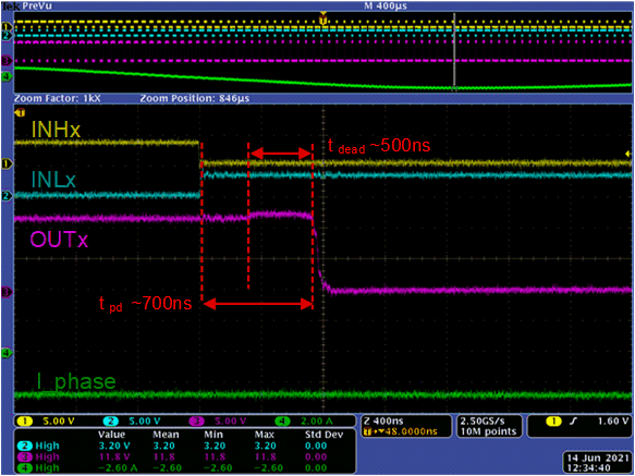
The example waveform in Figure 2-10 shows INHx falling and INLx rising and current is going out of the phase (positive current in green) for the DRV8316 with a slew rate of 200 V/µs and sinusoidal commutation. The dead time and propagation delay typical values in the DRV8316 data sheet specifications are 500 ns and 700 ns, respectively, with maximums included as well. Note how internal dead time is included into the propagation delay.
 Figure 2-10 Waveforms of Dead Time and Propagation Delay When INHx is Falling, INLx is Rising, and Current Flows Into OUTx
Table 4-1 summarizes all of the findings from this section for sinusoidal current, synchronous input PWMs in reference to a generalized typical propagation delay time and dead time for a slew rate setting.