SLVAF90 October 2021 TPS63805
1 Introduction
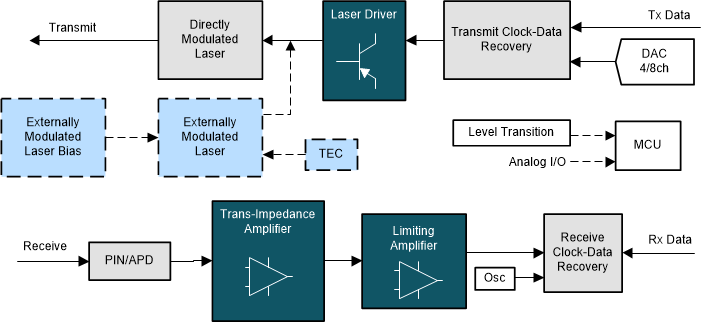
Optical modules are normally supplied from 3.3 V. However, the voltage deviation of initial power supply could be quite high, up to +/-10%. Additional details can be found in Buck-Boost Converters Solving Power Challenges in Optical Modules. Figure 1-1 shows the block diagram of optical module. The trans-impedance amplifier (TIA) on the receive side requires much higher voltage accuracy to guarantee its functionality and performance. To achieve this, a voltage stabilizer after initial 3.3 V power supply is necessary.
 Figure 1-1 Block Diagram of Optical Module
Considering that optical modules are hot-plugged and small-sized, voltage stabilizer in optical module has several requirements:
- A load capacity
- Smaller than 2mm×2mm size
- 90% efficiency. at least
- Maximum 10mV output voltage ripple