SLVAFG6B December 2022 – November 2024 TPS25762-Q1 , TPS25763-Q1 , TPS25772-Q1
5.3 Hybrid Mode Example
This section provides examples of power distribution when the Source ports are in Hybrid Mode. Table 5-10 shows the configurable SPM Engine parameters used in this section's example. Table 5-11 shows the Hybrid Mode parameters used in the power distribution method.
Table 5-10 SPM Engine Parameters - Hybrid
Mode Example
| SPM Engine Parameters | Configuration | Description |
|---|---|---|
| System Max Power | 54W(1) | Total system power capacity allocated for Port A and B |
| Port A Max Power | 45W | Maximum Port A Power |
| Port B Max Power | 45W | Maximum Port B Power |
| Port A Min Power | 9W | Minimum Port A power |
| Port B Min Power | 9W | Minimum Port B power |
| Assured Mode (2) | Max Init Power | Source initially sends Source Capabilities advertising max power |
(1) The System Max Power is 54W; less than the sum of Port A Max Power
and Port B Max Power. This is how Hybrid Mode is enabled from the GUI.
(2) Hybrid Mode is enabled with the Assured Capacity Policy selected
in the GUI configurations.
Table 5-11 Hybrid Mode Parameters
| Fair Share Power Policy Parameters | Value | Description |
|---|---|---|
| Equally Divided System Power | 54/2=27W | Equally divided System Max Power that is distributed to each port
when two PD-Sinks are connected: System Max Power / Total number of ports. |
| Single Port Max Power Capacity | 54-9 W=45W | System Max Power - Port Min Power (limited up to Port Max Power) |
| Non-PD USB-C Power | 15W | USB Type-C 5V output for non-PD based USB Type-C charging |
Three scenarios of Hybrid Mode power distribution are listed in Table 5-12 as examples.
Table 5-12 Hybrid Mode Example
| Port A | Port B | |
|---|---|---|
| Initially Allocated | 27W | 27W |
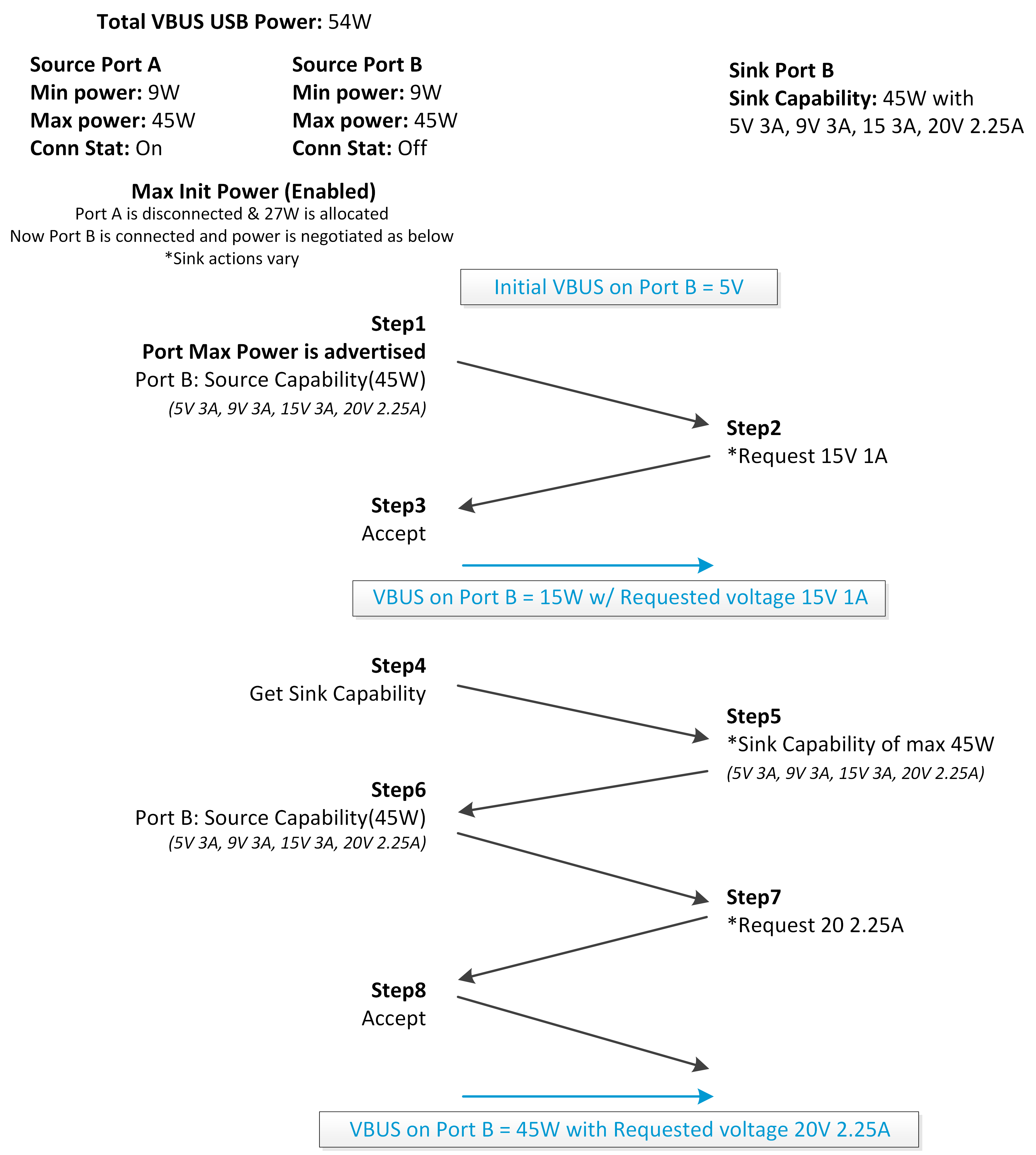
| Scenario 1: Port A is unconnected. Port B connects to a Sink that requires 45W. | ||
| Power Required by Sink | 45W | |
| Power Distributed to Sink | 45W | |
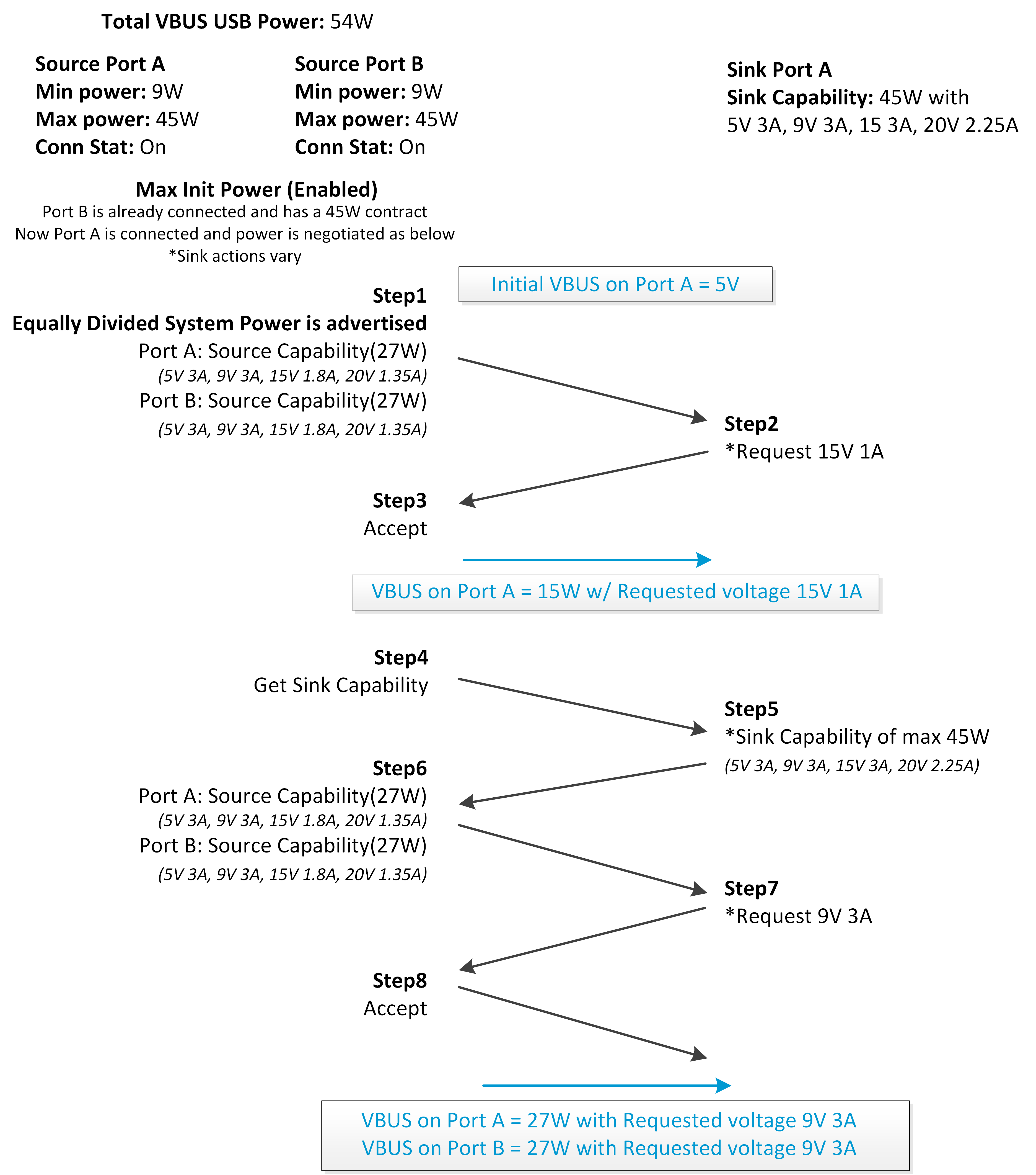
| Scenario 2: Port A connects to a Sink that also requires 45W. | ||
| Power Required by Sinks | 45W | 45W |
| Power Distributed to Sinks | 27W | 27W |
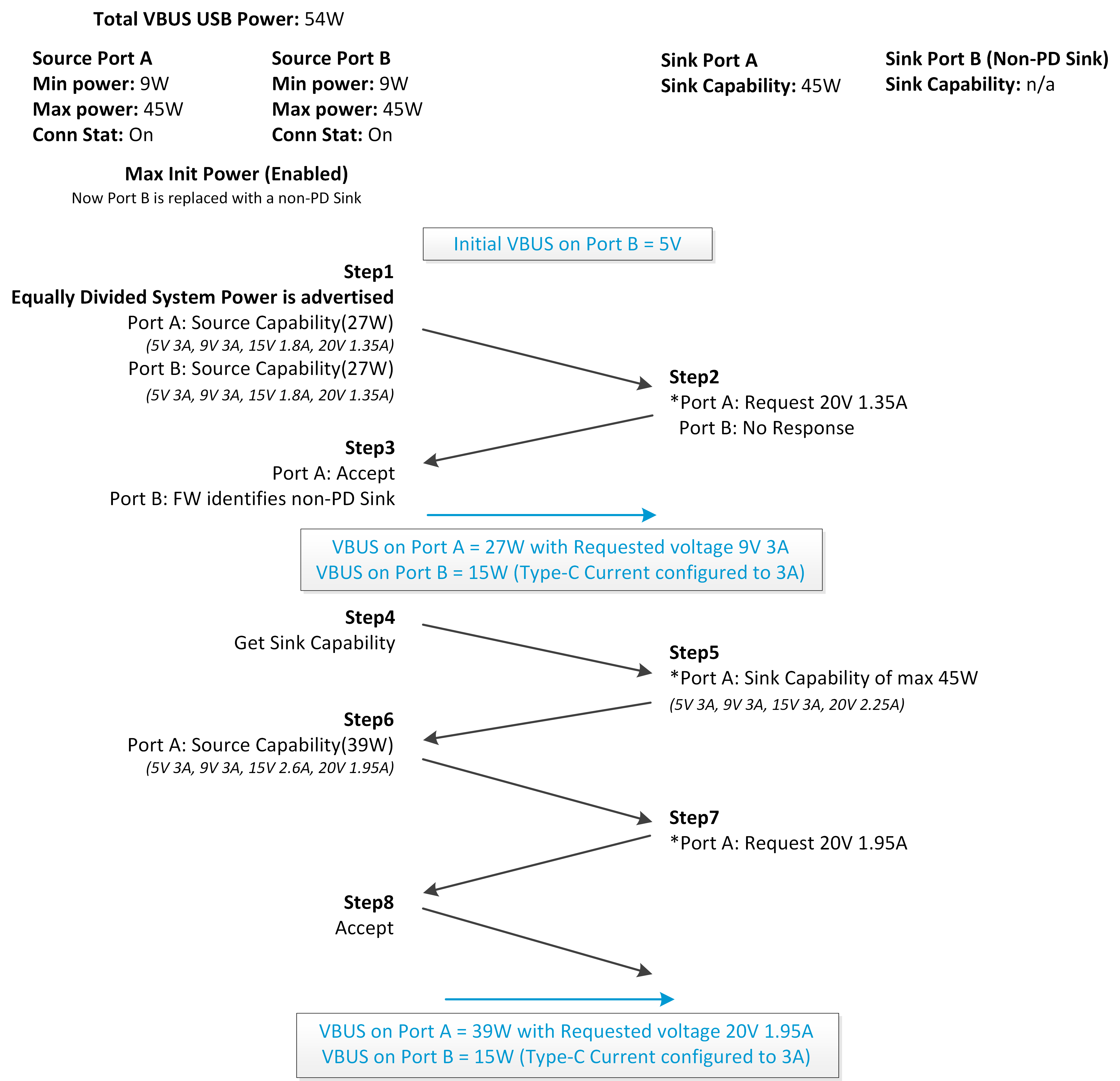
| Scenario 3: Port B's Port Partner is replaced with a non-PD Sink. | ||
| Power Required by Sink | 45W | |
| Power Distributed to Sinks(1) | 39W | 15W |
(1) Power distribution updates after roughly 8.5 seconds when
the TPS257xx-Q1 firmware identifies a non-PD Sink.
Figure 5-11, Figure 5-12, and Figure 5-13 show the PD negotiation flow following the Hybrid Mode examples from Scenario 1, Scenario 2, and Scenario 3 of Table 5-12, respectively.
 Figure 5-11 Hybrid Mode Negotiation Flow -
Scenario 1
 Figure 5-12 Hybrid Mode Negotiation Flow -
Scenario 2
 Figure 5-13 Hybrid Mode Negotiation Flow -
Scenario 3