SLVAFO8A April 2024 – May 2024 DRV8214 , DRV8234
- 1
- Abstract
- Trademarks
- 1Introduction: Need for Sensorless Designs
- 2Ripple Counting − Concept
- 3Case Study: Robotic Wheel Drive
- 4Challenges and Workarounds
- 5Summary
- 6References
- 7Revision History
2 Ripple Counting − Concept
Ripple Counting works by detecting current ripples that occur during commutation of the armature windings in a BDC motor. Commutation is the process of current reversal in the windings of a BDC motor to make sure that the motor torque remains in the same direction during motor operation. The contact brushes used with the commutator cause momentary short circuits in the motor windings which appear as ripples in the observed motor current waveform. Each commutation corresponds to one ripple. Thus, counting the number of ripples over one revolution of the motor helps estimate the position of the motor from the initial position.
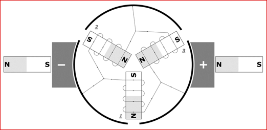
 Figure 2-1 DC Motor Construction with 2
brushes and 3 commutators
Figure 2-1 DC Motor Construction with 2
brushes and 3 commutatorsMeasuring the ripples per unit time provides the ripple speed (or ripple frequency), ωR in Hz. To convert into rad/s, use the following equation:
Knowing the number of commutator segments and brushes, the motor speed, ωM, can then be calculated by dividing the ripple frequency by the number of ripples per revolution. Number of ripples per revolution, NR, can be found by taking the lowest common multiple (LCM) of the number of brushes, NB, and the number of commutator segments, NC.
Hence, speed of the motor is given by:
Please note that LCM can be easily calculated using an online calculator.
As an example, from Figure 2-1, we see that NB =2, and NC=3. Hence, NR = LCM(2,3) = 6. This is verified by logic, since each brush short-circuits each pair of commutator segments once during each revolution. There are 2 brushes and 3 commutators causing 6 short circuits per revolution. As a result, there are 6 ripples per revolution. Figure 2-2 shows an example current waveform during steady state operation at 100% duty cycle.
 Figure 2-2 Brushed DC Motor Current
Waveform with Ripples