SLVAFW9 August 2024 LM51772
4.3.2 Comparison Between Single Phase and Dual Phase Operation
The thermal images are taken for both single-phase and dual-phase operations, to verify the thermal efficiency of the dual-phase operation. The thermal tests are taken for single phase and dual phase in buck, buck-boost, and boost operation at variable load. The thermal images show that the dual-phase operation has a lower temperature in comparison to the single-phase operation at the same load profile, as shown in Figure 4-19 to Figure 4-34. The equal load sharing of the total load current among two converters in dual phase results in less thermal losses and enhance the overall thermal efficiency of the converter.
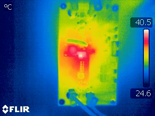 Figure 4-19 Thermal Condition in Single Phase Boost
(VIN=12V and 2A Load)
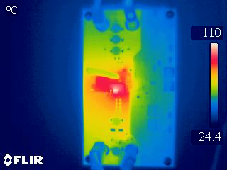 Figure 4-21 Thermal Condition in Single Phase Boost
(VINVin=12V and 8A Load)
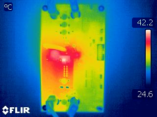 Figure 4-23 Thermal Condition in Single Phase Boost
(VIN=15V and 2A Load)
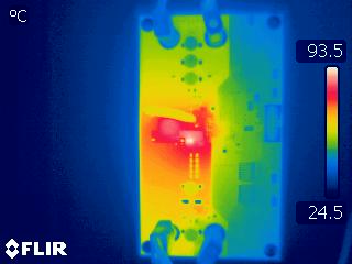 Figure 4-25 Thermal Condition in Single Phase Boost
(VIN=15V and 8A Load)
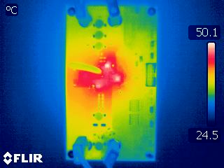 Figure 4-27 Thermal Condition in Single Phase Buck-Boost
(VIN=20V and 2A Load)
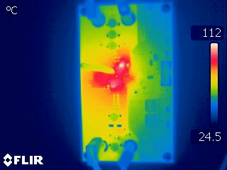 Figure 4-29 Thermal Condition in Single Phase Buck-Boost
(VIN=20V and 8A Load)
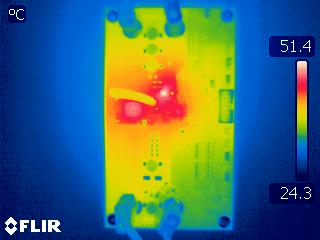 Figure 4-31 Thermal Condition in Single Phase Buck
(VIN=30V and 2A Load)
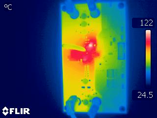 Figure 4-33 Thermal Condition in Single Phase Buck
(VIN=30V and 8A Load)
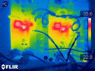 Figure 4-20 Thermal Condition in Dual Phase Boost
(VIN=12V and 2A Load)
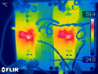 Figure 4-22 Thermal Condition in Dual Phase Boost
(VIN=12V and 8A Load)
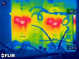 Figure 4-24 Thermal Condition in Dual Phase Boost
(VIN=15V and 2A Load)
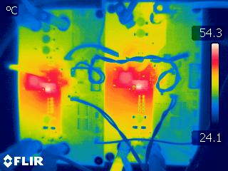 Figure 4-26 Thermal Condition in Dual Phase Boost
(VIN=15V and 8A Load)
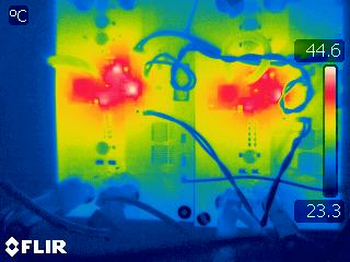 Figure 4-28 Thermal Condition in Dual Phase Buck-Boost
(VIN=20V and 2A Load)
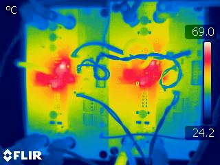 Figure 4-30 Thermal Condition in Dual Phase Buck-Boost
(VIN=20V and 8A Load)
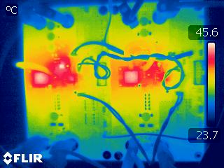 Figure 4-32 Thermal Condition in Dual Phase Buck
(VIN=30V and 2A Load)
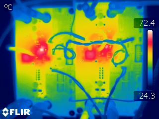 Figure 4-34 Thermal Condition in Dual Phase Buck
(VIN=30V and 8A Load)