SLVU944B October   2015  – October 2020 TPS7H1101-SP


  1.   Trademarks
  2. 1Introduction
    1. 1.1 Related Documentation
  3. 2Description
  4. 3Test Setup
    1. 3.1 Equipment
      1. 3.1.1 Power Supplies
      2. 3.1.2 Load Number 1
      3. 3.1.3 Meters
      4. 3.1.4 Oscilloscope
    2. 3.2 Bench Test Setup Conditions
      1. 3.2.1 Headers Description and Jumper Placement
      2. 3.2.2 Testing
    3. 3.3 Power-Up Procedure
      1. 3.3.1  IOUT and VOUT Measurements
      2. 3.3.2  Output Current Limiting
      3. 3.3.3  High-Side Current Sense
      4. 3.3.4  Current Foldback
      5. 3.3.5  Power Good
      6. 3.3.6  Dropout Voltage
      7. 3.3.7  Transient Response
      8. 3.3.8  Current Sharing
      9. 3.3.9  Soft-Start
      10. 3.3.10 Enable and Disable
      11. 3.3.11 Turn-Off
  5. 4Board Layout
    1. 4.1 EVM Layout Flexibility
  6. 5Schematic and Bill of Materials
  7.   Revision History

Current Sharing

For demanding load requirements, multiple LDOs can be paralleled.

  • In parallel mode CS pin of LDO#1 must be connected to PCL pin of LDO#2 via a series resistor
    (3.75 kΩ) and CS pin of LDO#2 must be connected to PCL pin of LDO#1 via series resistor (3.75 kΩ).
  • In parallel configuration R30 (resistor from PCL to GND) and R23 (resistor from CS pin to VIN) must be left open (unpopulated).
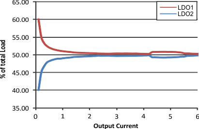
GUID-9AEC6531-4856-458D-A30A-E19DACD92CF8-low.gifFigure 3-10 Current Sharing LDO_1 and LDO_2