SLVUB95C December   2017  – August 2018 DRV10974


  1.   DRV10974 Evaluation Module
    1.     Trademarks
    2. DRV10974 EVM Kit Contents
    3. Introduction
      1. 2.1 Features
    4. Quick Start Guide
    5. DRV10974 Onboard Connections
      1. 4.1 Connector (P1) for Power Input
      2. 4.2 Interface Connector (P2) for Phase Windings of Motor
    6. DRV10974 Package
    7. User Interface
      1. 6.1 Jumpers
      2. 6.2 Switch
      3. 6.3 Test Points
    8. CS, RMP, and ADV Resistor Selection
      1. 7.1 CS Resistor Table
      2. 7.2 RMP Resistor Table
      3. 7.3 ADV Resistor Table
    9. Schematic
    10. Bill of Materials (BOM)
    11. 10 EVM Documentation
  2.   Revision History

Interface Connector (P2) for Phase Windings of Motor

Connector P2 is used to interface the U, V, and W phases. The pin assignments are as follows:
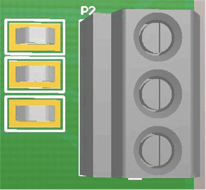
motor-phase-windings-input-terminal-block-p2.gifFigure 6. Motor Phase Windings Input Terminal Block (P2)

Table 2. Connector P2: 3-Terminal Connector to Connect 3-Phase BLDC Motor

TERMINAL DESCRIPTION
1(1) Phase-U
2 Phase-V
3 Phase-W
Note that terminal 1 is denoted by the small, silkscreened rectangle on the board at the right side of the terminal block.