SLVUBE6C November   2018  – July 2021 TPS56339


  1.   Trademarks
  2. 1Introduction
  3. 2Performance Specification Summary
  4. 3Modifications
    1. 3.1 Output Voltage Set Point
    2. 3.2 Adjustable UVLO
  5. 4EVM Photos
  6. 5Test Setup and Results
    1. 5.1  Input/Output Connections
    2. 5.2  Start-Up Procedure
    3. 5.3  Efficiency
    4. 5.4  Output Voltage Load Regulation
    5. 5.5  Output Voltage Line Regulation
    6. 5.6  Load Transients
    7. 5.7  Voltage Ripple
    8. 5.8  Powering Up
    9. 5.9  Powering Down
    10. 5.10 Output Short Protection and Recovery
    11. 5.11 Thermal Performance
  7. 6Board Layout
    1. 6.1 Layout
  8. 7Schematic and List of Materials
    1. 7.1 Schematic
    2. 7.2 List of Materials
  9. 8Revision History

Adjustable UVLO

The under voltage lock out (UVLO) can be adjusted externally using R1 and R2. The EVM is set for a start voltage of 6.6 V and a stop voltage of 5.7 V using R1 = 174 kΩ and R2 = 36.5 kΩ. Use Equation 2 and Equation 3 to calculate required resistor values for different start and stop voltages. For higher light-load efficiency, consider choosing a larger R1 and R2. Make adjustments to Vstart or Vstop for a proper R1. Once R1, R2 settled down, the VEN voltage need to be calculated by Equation 4 to make sure that it is lower than 5.5V with max VIN, max Ip and max Ih.

Equation 2. GUID-4B5081F6-AFFC-47F4-B41D-92C961D0C4B3-low.gif
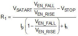
Equation 3. GUID-D0BAAFED-46B3-4436-A9FC-8E4DD145BA1D-low.gif
Equation 4. GUID-3EF328BF-15E3-464B-904B-B94C094C4FE2-low.gif

where

  • Ip = 1.2 µA
  • Ih = 3.1 µA
  • VENfalling = 1.12 V
  • VENrising = 1.18 V