SLVUBJ9A July 2020 – October 2020 TPS54JB20
2.8 Powering Up
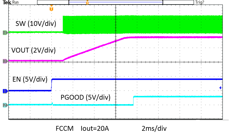
Figure 2-8 shows the start-up waveforms for the TPS54JB20EVM. This images shows that the start-up sequence begins as soon as the EN voltage is increased above the enable-threshold voltage, and the output voltage ramps up to the externally set value of 1.0 V. The input voltage for these plots is 12 V.
 Figure 2-8 TPS54JB20
Enable Start-Up, 20-A Load