SLVUC02B September 2020 – May 2021 TPSM41615 , TPSM41625
4 Performance Data
Figure 4-1 and Figure 4-2 demonstrate the enable ON/OFF performance of the EVM. See Figure 4-3 through Figure 4-5 for transient response waveforms (5-A, 10-A and 15-A load with a scale of 10 A/uS) associated with the default populated EVM. Figure 4-6 shows the typical output voltage ripple with a 15-A load. Additional output capacitor footprints are available on the EVM if an improved load transient response or output voltage ripple is needed. See the data sheet for more information on the respective devices.
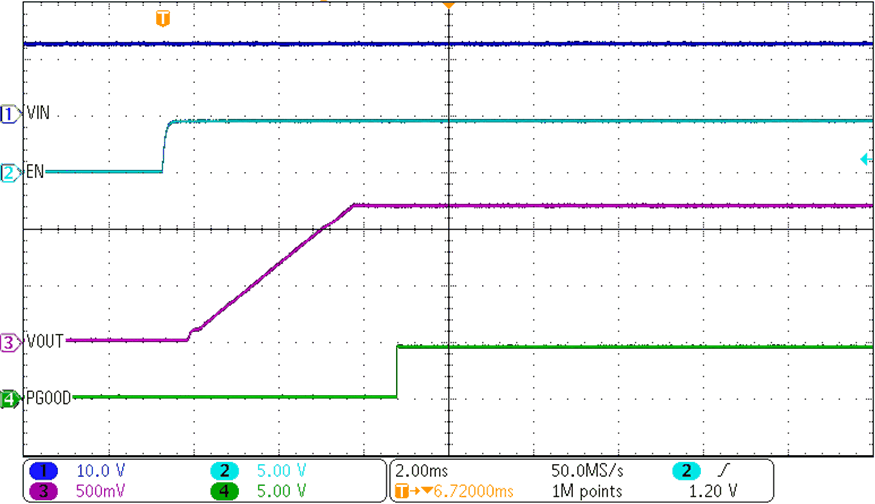 Figure 4-1 ENABLE Start-Up
Waveform
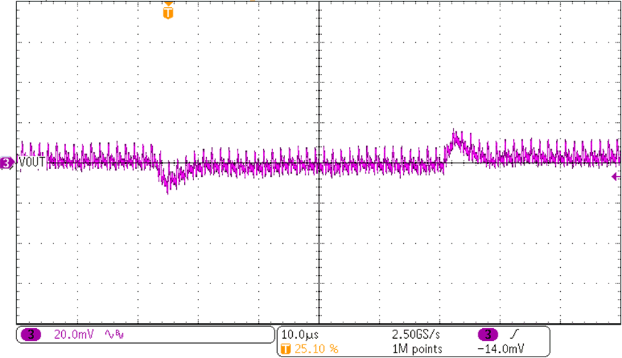 Figure 4-3 5-A Transient Performance
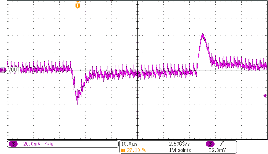 Figure 4-5 15-A Transient Performance
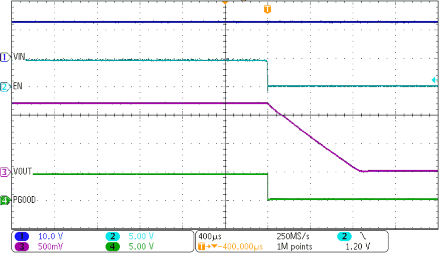 Figure 4-2 ENABLE Shutdown
Waveform
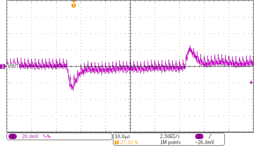 Figure 4-4 10-A Transient Performance
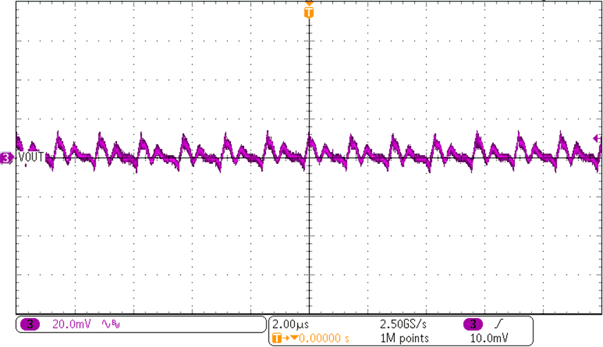 Figure 4-6 15-A Output Voltage
Ripple