SLVUCA1 November 2021 TPS7H1210-SEP
6 Board Layout
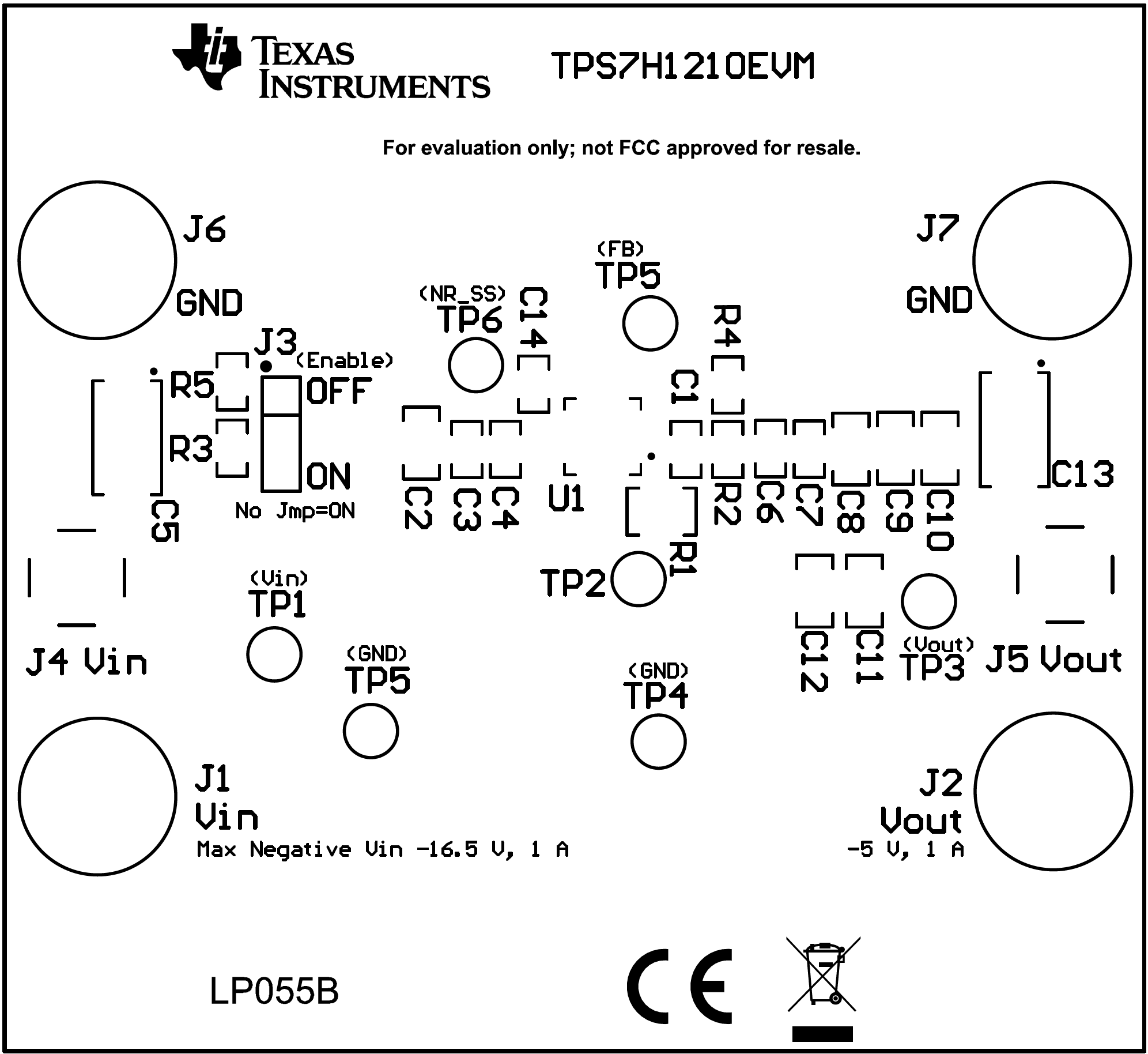
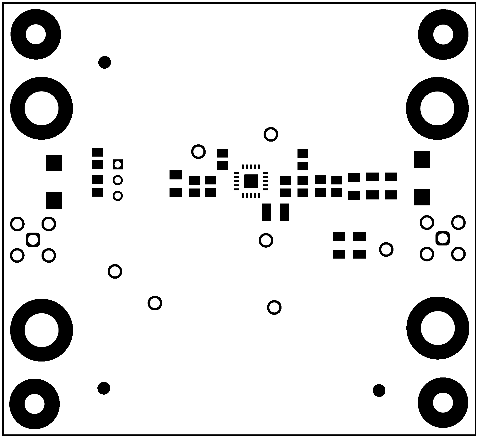
The following images represent the board design layers.
 Figure 6-1 Top Overlay Silkscreen
 Figure 6-2 Top Solder Mask
 Figure 6-3 Top Signal Layer
 Figure 6-4 Bottom Signal Layer