SLVUCF6 july 2023
- 1
- Abstract
- Trademarks
- 1Introduction
- 2Requirements
- 3TPS65219 Resources Overview
- 4EVM Configuration
- 5NVM Programming
- 6Graphical User Interface (GUI)
- 7Schematics, PCB Layouts, and Bill of Materials
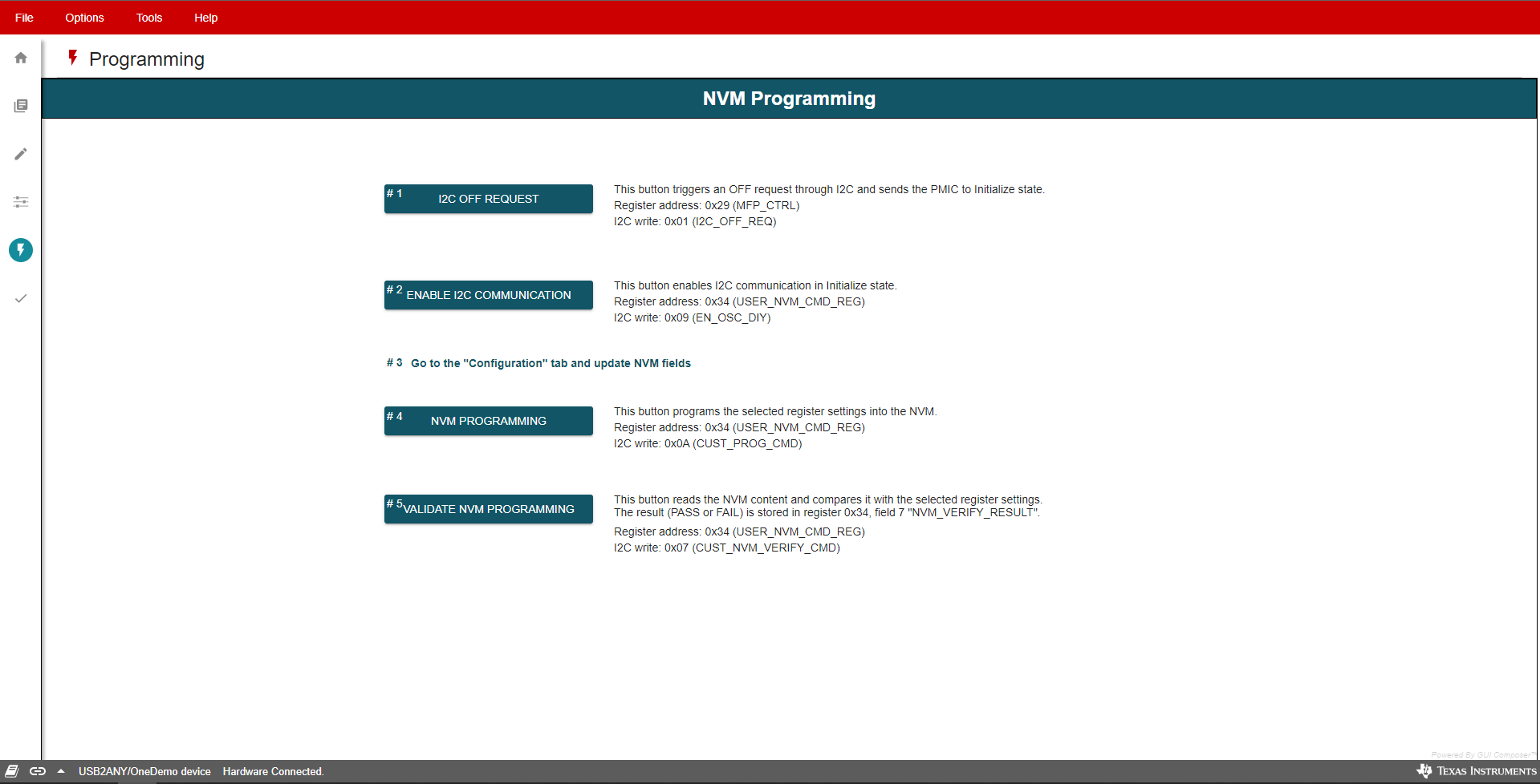
6.8 NVM Programming Page
The NVM Programming page allows re-programming the device NVM memory to change the default register settings. This page includes four main functions that correspond to the buttons shown in Figure 6-12. The first two steps “I2C OFF REQUEST” and “ENABLE I2C COMMUNICATION” are only needed when re-programming the PMIC from the Initialize state (PMIC rails OFF).
- The I2C OFF REQUEST button triggers an OFF request though I2C and sends the PMIC to INITIALIZE state.
- The ENABLE I2C
COMMUNICATION button enables I2C communication in INITIALIZE
state.
- Once I2C communication is enabled, you can go to the NVM configuration page to select the desired register settings or use the File tab options to load a pre-configured JSON or CSV file.
- The NVM PROGRAMMING button programs the selected register settings into the NVM.
- The VALIDATE NVM PROGRAMMING button reads the NVM content and compares it with the selected register settings. The result (PASS or FAIL) is stored in register 0x34, field 7 “NVM_VERIFY_RESULT".
 Figure 6-12 NVM Programming
Page