SLVUCF6 july   2023


  1.   1
  2.   Abstract
  3.   Trademarks
  4. 1Introduction
  5. 2Requirements
    1. 2.1 Hardware
    2. 2.2 Software
  6. 3TPS65219 Resources Overview
  7. 4EVM Configuration
    1. 4.1 Configuring the USB to I2C Adapter
    2. 4.2 Configuration Headers
    3. 4.3 Test Points
  8. 5NVM Programming
    1. 5.1 TPS65219EVM-SKT default NVM settings
    2. 5.2 NVM programming in Initialize State
    3. 5.3 NVM programming in Initialize State
  9. 6Graphical User Interface (GUI)
    1. 6.1 TPTS65219 EVM Debugging
    2. 6.2 I2C Communication Port and Adapter Debugging
    3. 6.3 Getting Started
      1. 6.3.1 Finding the GUI
      2. 6.3.2 Downloading the Required Software
      3. 6.3.3 Launching the GUI
      4. 6.3.4 Connecting to the EVM
    4. 6.4 Collateral Page
    5. 6.5 Register Map Page
    6. 6.6 NVM Configuration Page
      1. 6.6.1 NVM Fields
      2. 6.6.2 Create / Load a Custom Configuration
    7. 6.7 Sequence Configuration
    8. 6.8 NVM Programming Page
    9. 6.9 Additional Features
  10. 7Schematics, PCB Layouts, and Bill of Materials
    1. 7.1 TPS65219EVM-SKT Schematic
    2. 7.2 TPS65219EVM-SKT PCB Layers
    3. 7.3 TPS65219EVM-RSM Schematic
    4. 7.4 TPS65219EVM-RSM PCB Layers
    5. 7.5 Bill of Materials

NVM Configuration Page

The NVM Configuration page (shown in Figure 6-9) is the main feature of the GUI and highlights the configurability of the PMIC. On this page, register fields are grouped according to their use case and are labeled to indicate which part of the PMIC is controlled by each block. The NVM configuration page also provides the interface to save a custom configuration or load an existing configuration into the NVM of the target device. A full register read can be done using the READ ALL REGISTERS button in the top left of the page.
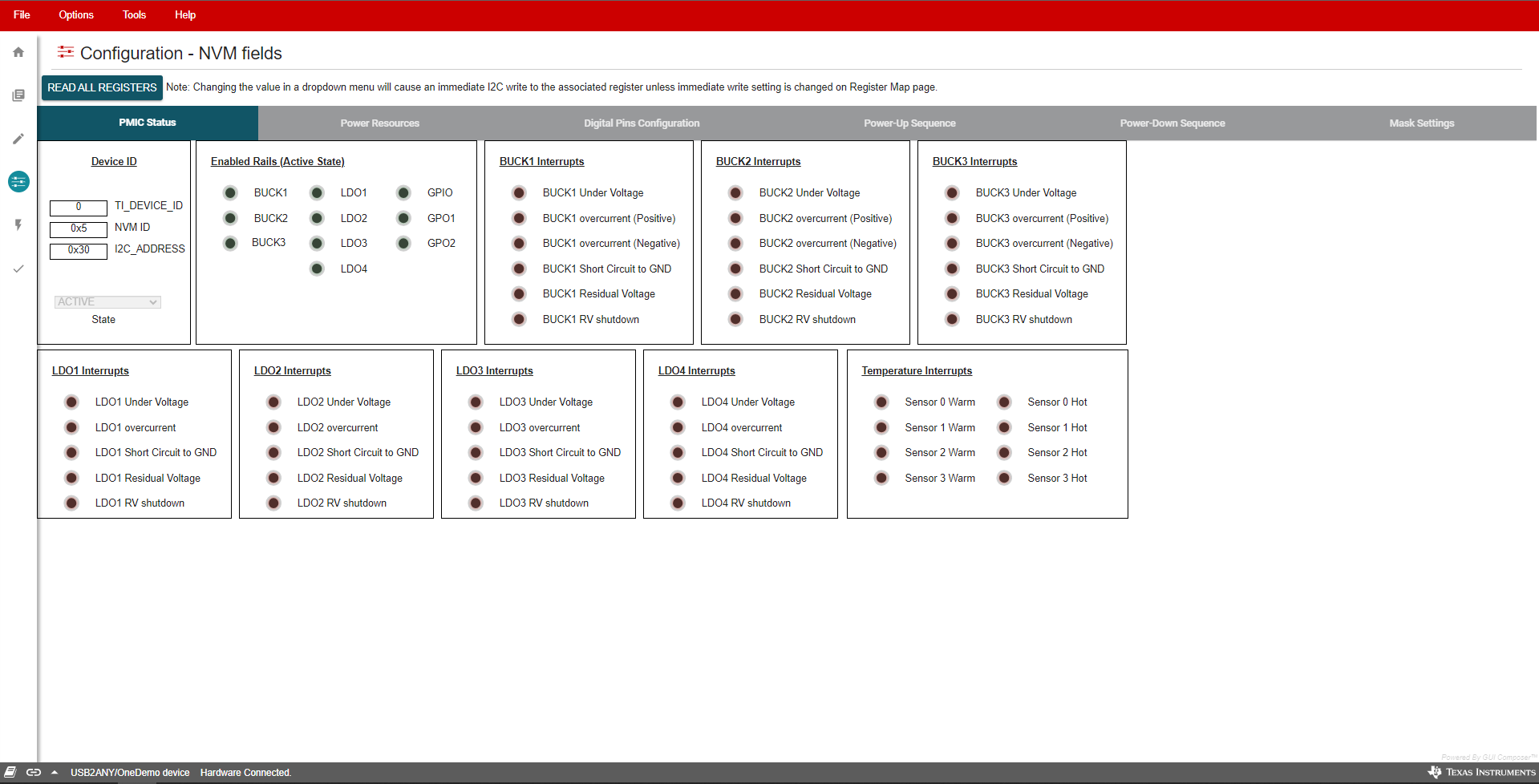
GUID-E00B2508-137A-4DD6-9C86-6794BA867742-low.png Figure 6-9 NVM Configuration Page