SLVUCP8 September 2024 TPS26750
- 1
- Description
- Get Started
- Features
- Applications
- 6
- 1Evaluation Module Overview
- 2Hardware
-
3Software
- 3.1 Software Description
- 3.2 Software Installation
- 3.3 Software Development
- 3.4 Using the Application Customization Tool
- 4Application Specific Use Cases
- 5Hardware Design Files
- 6Additional Information
2.8 Debug Information
One of the most valuable tools users can utilize when debugging USB-PD capable systems for a faster time-to-market is a USB-PD protocol analyzer. The USB-PD specification details how information is sent on the Configuration Channel (CC) lines between port partners, and the above mentioned analyzers can decode this traffic into an easily navigable log of events. These tools also show the voltage on the CC pins of the DUT for reviewing the Type-C implicit contract behavior. Utilizing this tool in conjunction with a 5V or 10V logic analyzer to view the signals available on headers J2 and J5, is a good place to start with debugging the TPS26750EVM.
When deciding which USB-PD analyzer to use, make sure that the analyzer is designed for use with EPR capable devices. The only one on the market below 200 USD, at the time of this document's initial publication, is the Power-Z KM003C. To log USB-PD traffic between port partners with the Power-Z KM003C, use the device in passthrough mode in conjunction with a computer. For information on how to use the Power-Z KM003C in passthrough mode, refer to the documentation manufacturer.
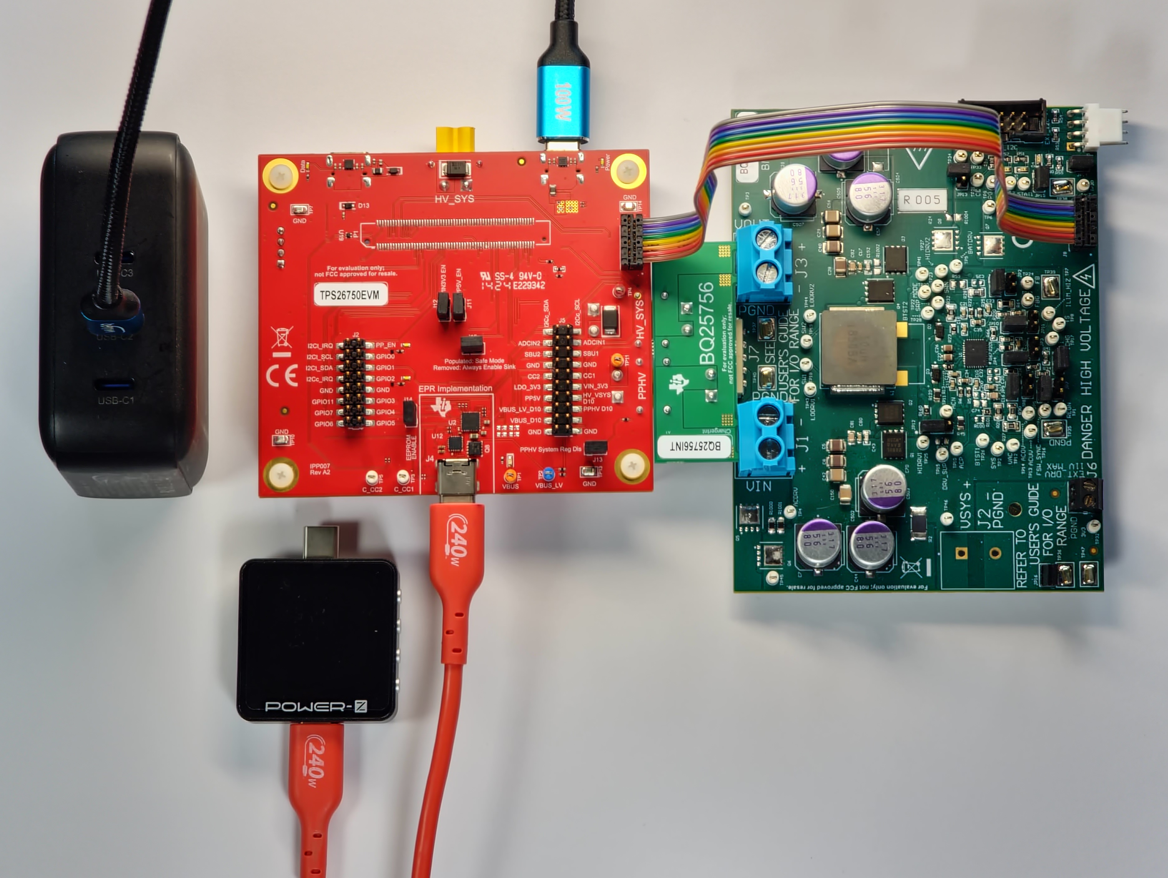
This device can also step through USB-PD contracts (Power Data Objects or PDOs) when acting as a power sink to relation to the port partner, the TPS26750 DUT (source), to test the TPS26750EVM's ability to source each PDO. This device is shown with a setup that allows users to test the configured USB-PD contracts (PDOs) of the TPS26750EVM with integrated control of the BQ25756EVM; see Figure 2-11.

Figure 2-11 Testing Setup Utilizing the Power-Z to Test Source PDOs of TPS26750EVM
Targeted Debugging
If users are not seeing expected behavior after configuring the TPS26750 using the Application Customization Tool, then one of the first places to start is to monitor the I2Cc lines when the TPS26750EVM is first powered up to see if the EEPROM is successfully writing the configuration of the device to the TPS26750. There must be I2C traffic (from the EEPROM to the TPS26750) that matches the contents of the binary that is exported from the Export Full Flash Binary tool in the GUI.
To successfully test the USB-PD Extended Power Range (EPR) with the TPS26750EVM, successfully negotiate an EPR contract (a USB-PD contract with a voltage greater than 20V), a USB-IF compliant 240W rated USB-C to USB-C cable must be used. If users are able to negotiate SPR contracts, but not EPR contracts, make sure the USB-C to USB-C cable is 240W rated.
If VBUS is falling (hitting UVLO) after a USB-PD EPR contract is negotiated while sourcing and utilizing the BQ25756EVM, then check to see if the power source connected to the HV_SYS net (either through J8 or J3) is capable of supplying sufficient current for the contract negotiated. For details on using the BQ25756EVM in conjunction with the TPS26750EVM, see Section 4.2.