SLVUCP8 September 2024 TPS26750
- 1
- Description
- Get Started
- Features
- Applications
- 6
- 1Evaluation Module Overview
- 2Hardware
-
3Software
- 3.1 Software Description
- 3.2 Software Installation
- 3.3 Software Development
- 3.4 Using the Application Customization Tool
- 4Application Specific Use Cases
- 5Hardware Design Files
- 6Additional Information
5.2 PCB Layouts
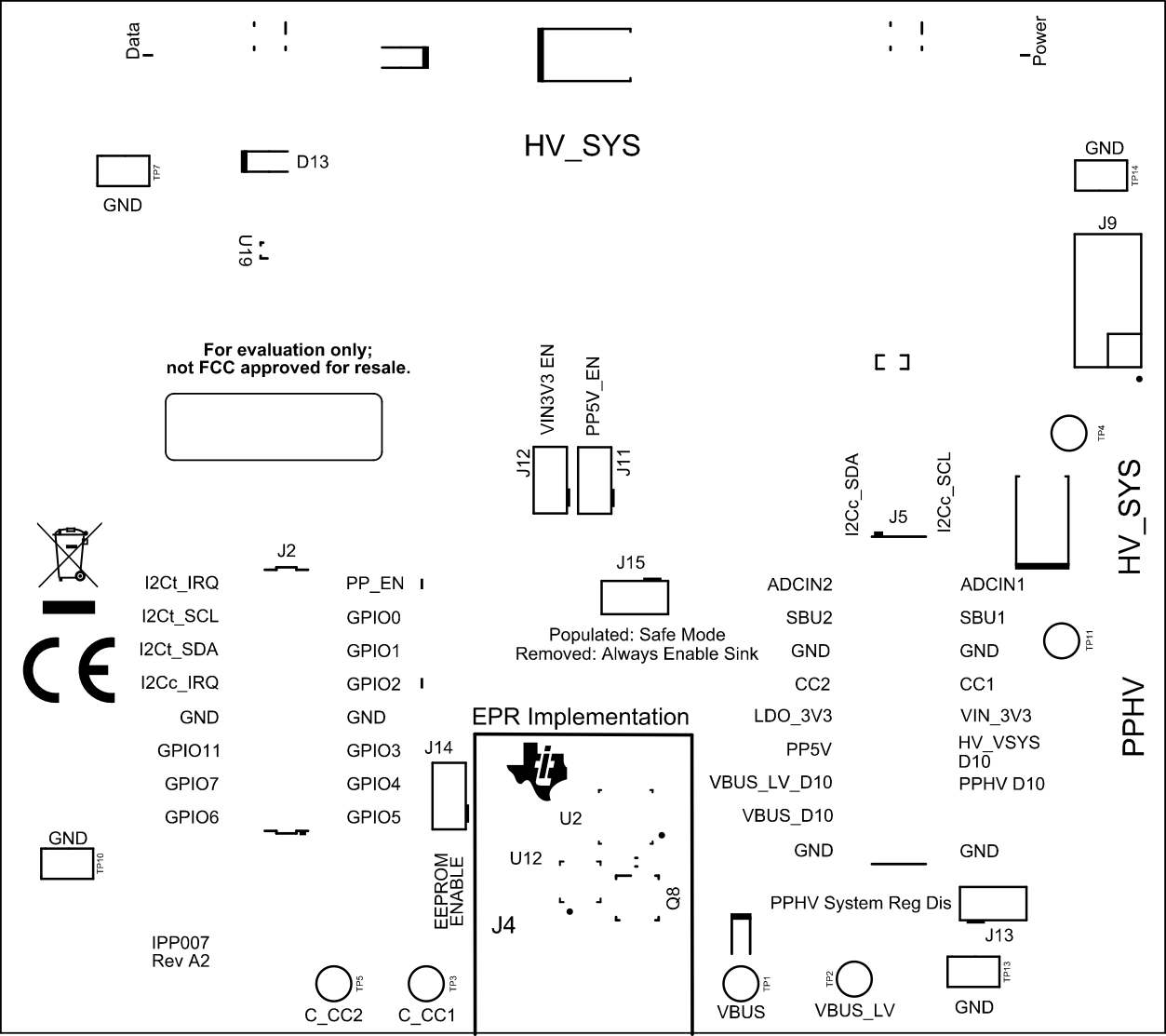 Figure 5-12 TPS26750EVM Top Layer
(Composite View)
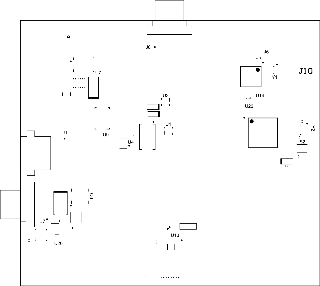 Figure 5-13 TPS26750EVM Bottom Layer
(Composite View)
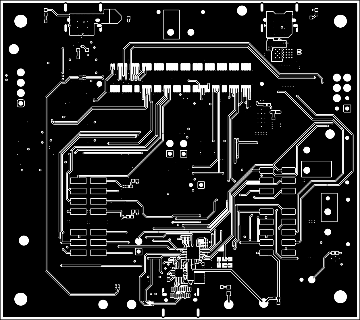 Figure 5-14 TPS26750EVM Top Layer
 Figure 5-15 TPS26750EVM GND Layer
 Figure 5-16 TPS26750EVM Internal Layer
1
 Figure 5-17 TPS26750EVM Internal Layer
2
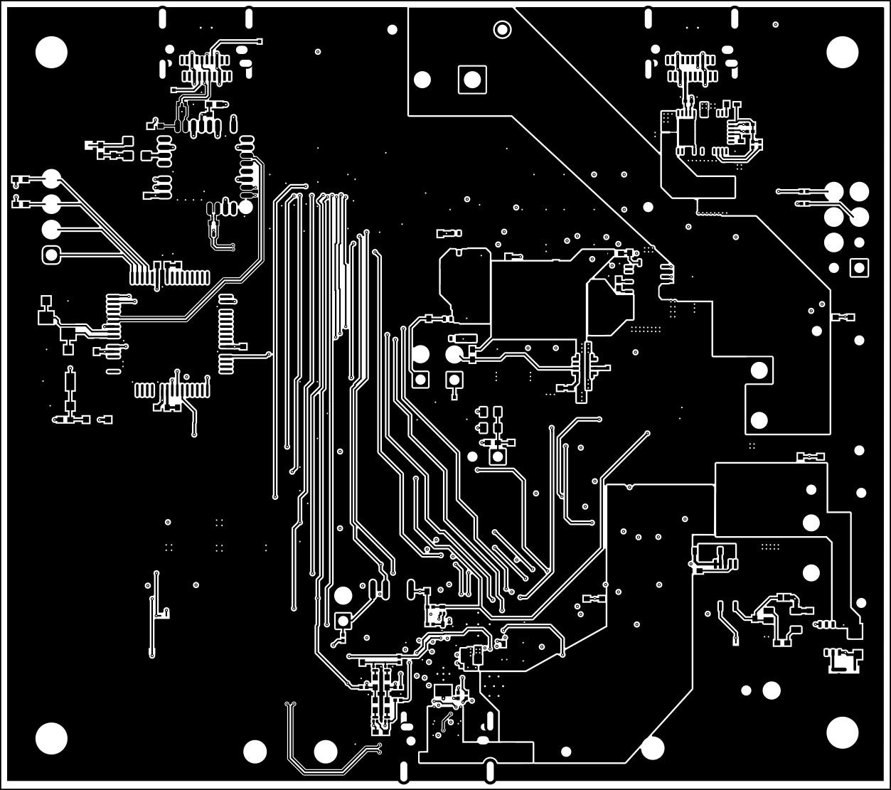 Figure 5-18 TPS26750EVM Bottom
Layer
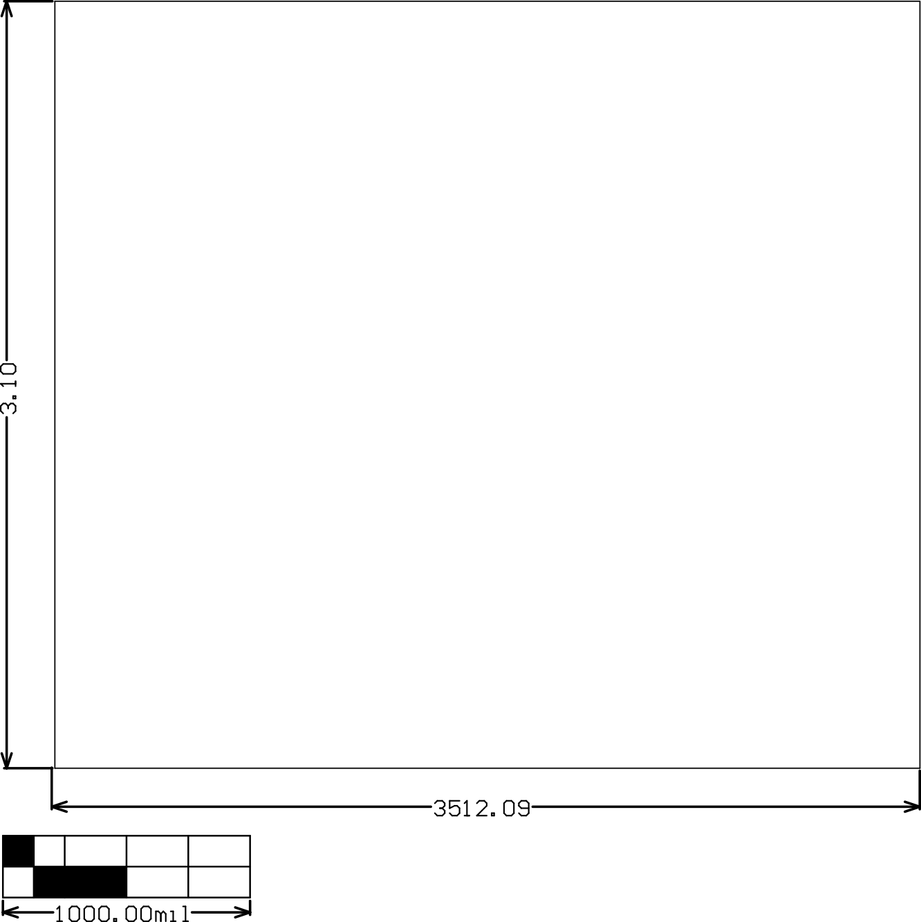 Figure 5-19 TPS26750EVMEVM Board
Dimensions