SLVUCT9 January   2024


  1.   1
  2.   Description
  3.   Features
  4.   Trademarks
  5. 1Evaluation Module Overview
    1. 1.1 Introduction
    2. 1.2 Kit Contents
    3. 1.3 Specification
      1. 1.3.1 Alternate Board Configurations
    4. 1.4 Device Information
  6. 2Hardware
    1. 2.1 Power Requirements
    2. 2.2 Important Usage Notes
    3. 2.3 Connector Descriptions
  7. 3Implementation Results
    1. 3.1 Default Configuration Results
    2. 3.2 Sequence UP and DOWN Thresholds
    3. 3.3 Delay Timer
    4. 3.4 Regulation Timer
    5. 3.5 Disabled Channels
    6. 3.6 Externally Induced System RESET
  8. 4Hardware Design Files
    1. 4.1 Schematics
    2. 4.2 PCB Layouts
    3. 4.3 Bill of Materials (BOM)
  9. 5Compliance Information
    1. 5.1 Compliance and Certifications
  10. 6Additional Information
    1. 6.1 Known Hardware Issues
  11. 7Related Documentation
  12. 8Revision History

Delay Timer

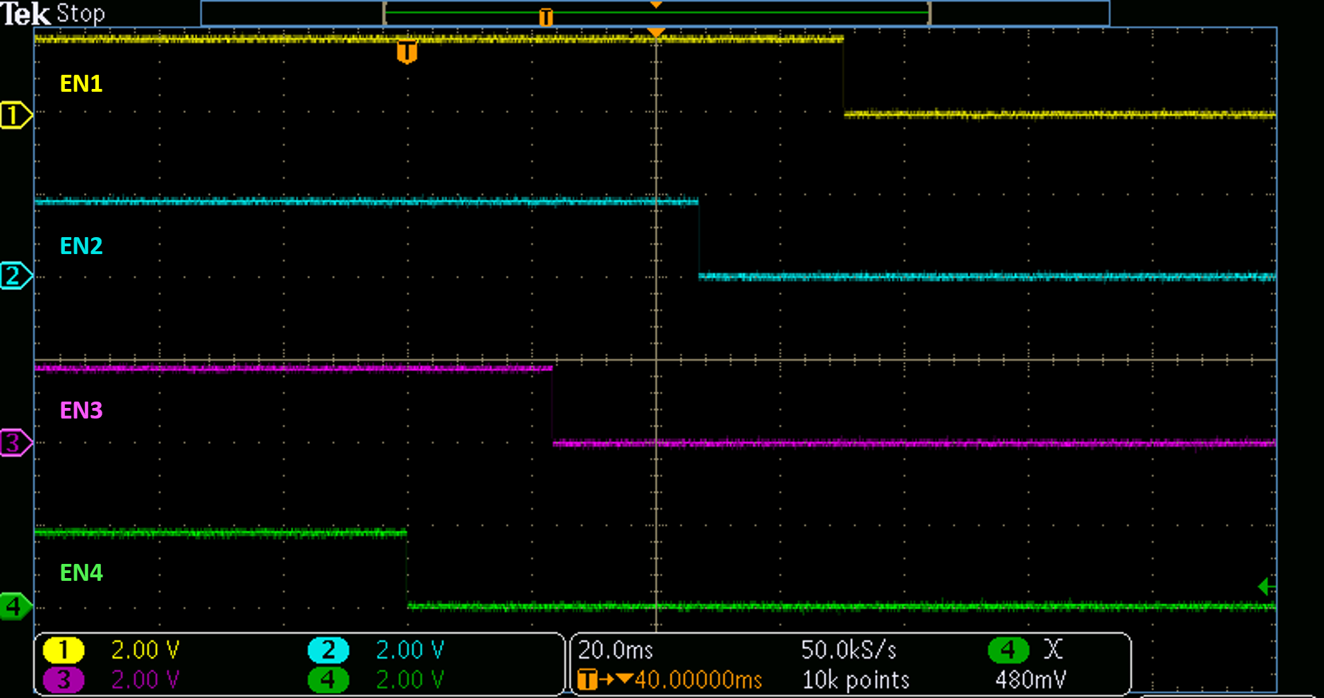
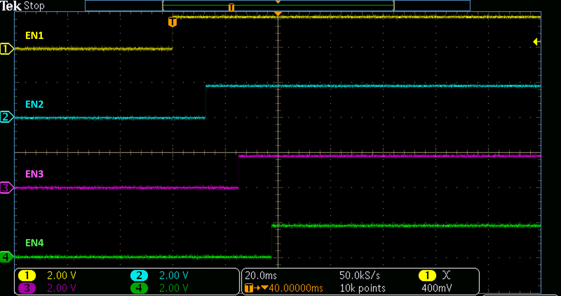
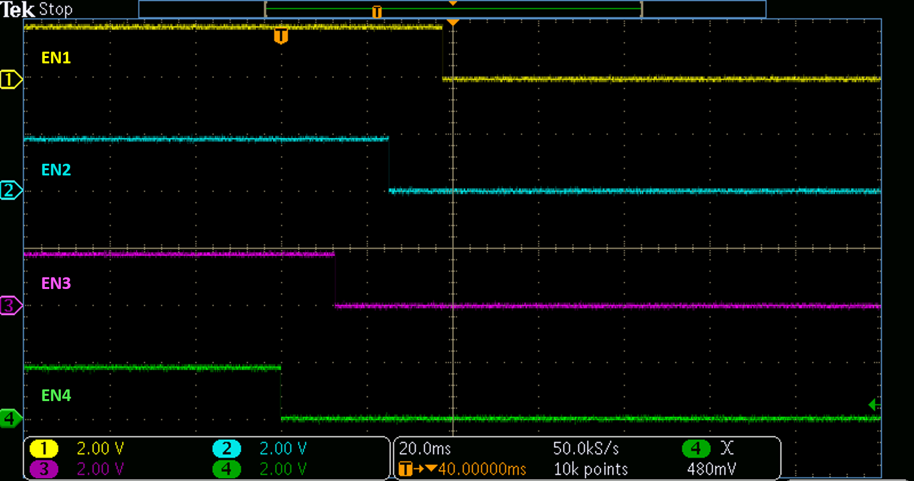
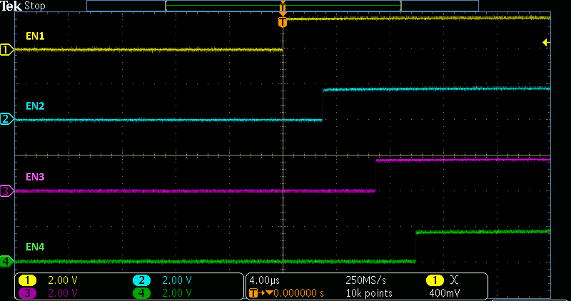
The shunt and resistor used on the DLY_TMR pin set the delay time that occurs between when the condition for an ENx signal to transition HIGH or LOW is met and when the ENx signal transitions.
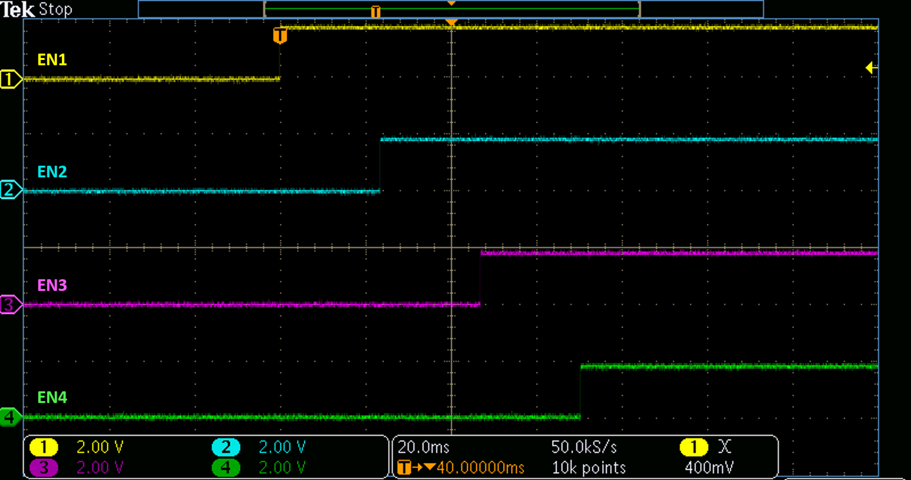
GUID-DB2194C6-DFC8-4207-9E91-25DD81950A9B-low.pngFigure 3-3 Sequence UP, 23ms Delay
GUID-90213BC1-1916-41D3-A714-CBC047A670F5-low.pngFigure 3-4 Sequence DOWN, 23ms Delay
GUID-52118274-C032-43A1-B264-1ED89EDA2A5B-low.pngFigure 3-5 Sequence UP, 12ms Delay
GUID-FD77A7E5-E49B-4D2A-A4BB-449A1C9D5A86-low.pngFigure 3-6 Sequence DOWN, 12ms Delay
GUID-5390BF75-29FE-445B-A64F-D9A525049047-low.pngFigure 3-7 Sequence UP, DLY_TMR Floating
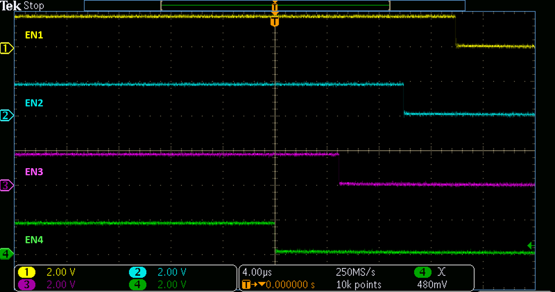
GUID-24E7662F-258D-453F-944C-A1EB718A473C-low.pngFigure 3-8 Sequence DOWN, DLY_TMR Floating