SLVUCX2 June 2024
2.2 Faults, Indicators, and Jumper Settings
The DRV8351 implements bootstrap undervoltage, GVDD undervoltage, and thermal shutdown in case of overtemperature. See the DRV8351 data sheet for more information on DRV8351 fault support.
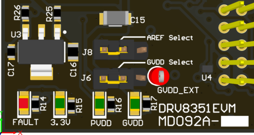
The DRV8351EVM implements overvoltage and undervoltage on the PVDD and GVDD supplies as well as gross over-current protection. Status LEDs for the 3.3V, PVDD, GVDD, and FAULT are included and shown below.
 Figure 2-6 Status LEDs, AREF Select, and GVDD Select
The FAULT LED lights up if the EVM senses a fault due to the following conditions:
| FAULT | Lower Limit | Upper Limit | Action Taken |
|---|---|---|---|
| PVDD | 6V | 100V | PWM Input forced to 0%. |
| GVDD | 6V | 20V | PWM Input forced to 0%. |
| Over-Current | -25A | 25A | PWM Input forced to 0%. |
The Faults can be reset in the GUI software using the CLEAR FAULTS button. More details on the GUI can be found in the Software section below.
The AREF Select jumper selects the offset for the Current Shunt Amplifiers on the EVM. The default position is to the left on pins 1:2 which configures the CSA for Bi-directional mode (offset 1.65V) allowing the CSA input to sense positive or negative current. Placing the jumper to the right on pins 2:3 configures the CSA for Unidirectional mode (offset 0V) which allows only positive currents to be measured. This does increase the measurement range of the CSA.
The GVDD Select jumper allows the user to use the built-in 12V Buck Regulator to generate GVDD or input externally through GVDD_EXT. The default position is to the left on pins 1:2, which configures the EVM for internal mode (GVDD from the buck regulator). Placing the jumper to the right on pins 2:3 configures the board for external GVDD mode (GVDD supplied into GVDD_EXT test point).