SLVUCX2 June 2024
2.1 Hardware Connections Overview
The following section describes the EVM hardware and connections to the external supply, hall sensors, PC via USB, and motor.
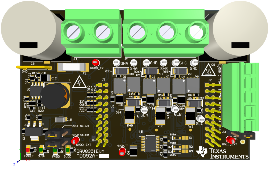 Figure 2-1 EVM Board Overview
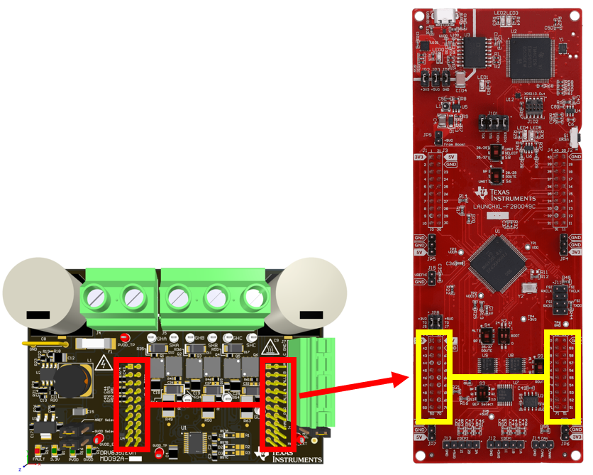 Figure 2-2 DRV8351EVM Connecting to
LAUNCHXL-F280049C
Figure 2-2 DRV8351EVM Connecting to
LAUNCHXL-F280049CThe DRV8351EVM must plug into the lower LAUNCHXL-F280049C LaunchPad headers as shown below.
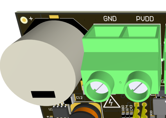 Figure 2-3 PVDD Input (J4)
To minimize the risk of potential shock hazard and personal injury, remove all power connections and interfaces to the DRV8351EVM when not in use.
The DRV8351EVM is designed for an input supply from 6VDC to 100VDC and up to 25A continuous drive current (software limited). The input connects to J4 with the noted polarity. PVDD_TP connects to the same node but must not be used for high current input. PVDD input is fused with a 30A fuse and the input connector is rated for 32A.
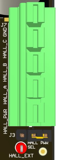 Figure 2-4 Hall Sensor Input and Power Connections (J7)
Hall sensors are connected to J7 including hall power and GND. The 3.3VDC supply to the Hall sensors is supplied from the 3.3V LDO on the EVM. External hall power can be input through the HALL_EXT test point if a different supply or voltage level is desired. To use the included 3.3V LDO to power the halls, connect J3 on the right side to pins 1:2 as shown. To use HALL_EXT, connect J3 on the left side to pins 2:3. To insert or remove wires/terminals on J7, use a flat blade screwdriver to push down the respective tab on top of the J7 connector.
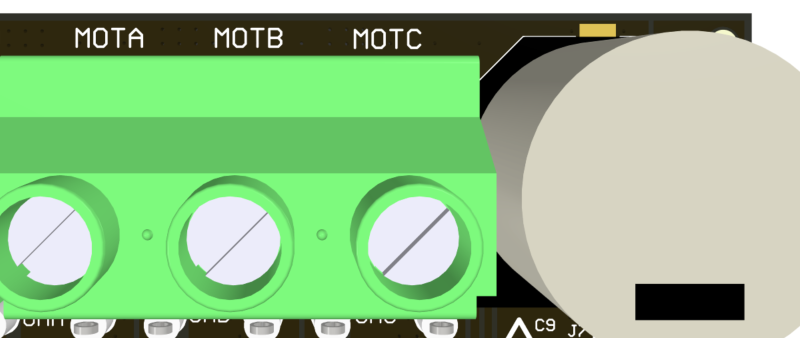 Figure 2-5 Motor Phase Connector
(J5)
Figure 2-5 Motor Phase Connector
(J5)Motor Phase connections must match the hall sensor connection sequence. For example, MOTA must match HALL_A, MOTB must match HALL_B, MOTC must match HALL_C. The phases must also be in sequential order; A, then B, then C.
If the motor phases do not match the hall sensors or the connections are made out of order, then the motor does not spin smoothly and current consumption increases.
The three phase inputs of the motor connect to MOTA/MOTB/MOTC through connector J5.