SLVUCX2A June 2024 – January 2025
2.3 EVM Hardware Quick-Start
This section describes the steps to prepare the DRV8351EVM for first motor spin-up. This section assumes the default jumper positions mentioned above are used.
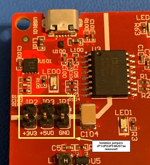
 Figure 2-7 JP1/JP2/JP3 Removed
- Make sure that the isolation jumpers JP1/JP2/JP3 on the LAUNCHXL-F280049C have been removed.
- Plug the DRV8351EVM onto the lower position of the LAUNCHXL-F280049C board.
- Connect motor phase connections to the respective MOTA/MOTB/MOTC inputs on J5, making sure to match A, B, and C.
- Connect the hall sensor connections, hall power, and ground to J7. Make sure that Hall A, B, and C are in the correct order.
- Connect the provided micro-USB cable to the LAUNCHXL-F280049C.
- Connect PVDD and GND to connector J4. A low current limit of 300mA on the PVDD supply is recommended for first power-up to make sure the EVM is connected correctly. If there is no issue upon power-up, then the current limit can be raised to allow for current based on your motor specifications.
- Start the GUI per the instructions below in the software section.