SLVUCX2A June 2024 – January 2025
3.1 DRV8351 EVM GUI Software
This section details the features of the EVM GUI Software. The GUI is written in GUI Composer and is available on the development software gallery at dev.ti.com/gallery. Once logged into the TI system, if users cannot find the GUI, then users need to request access from a TI representative.
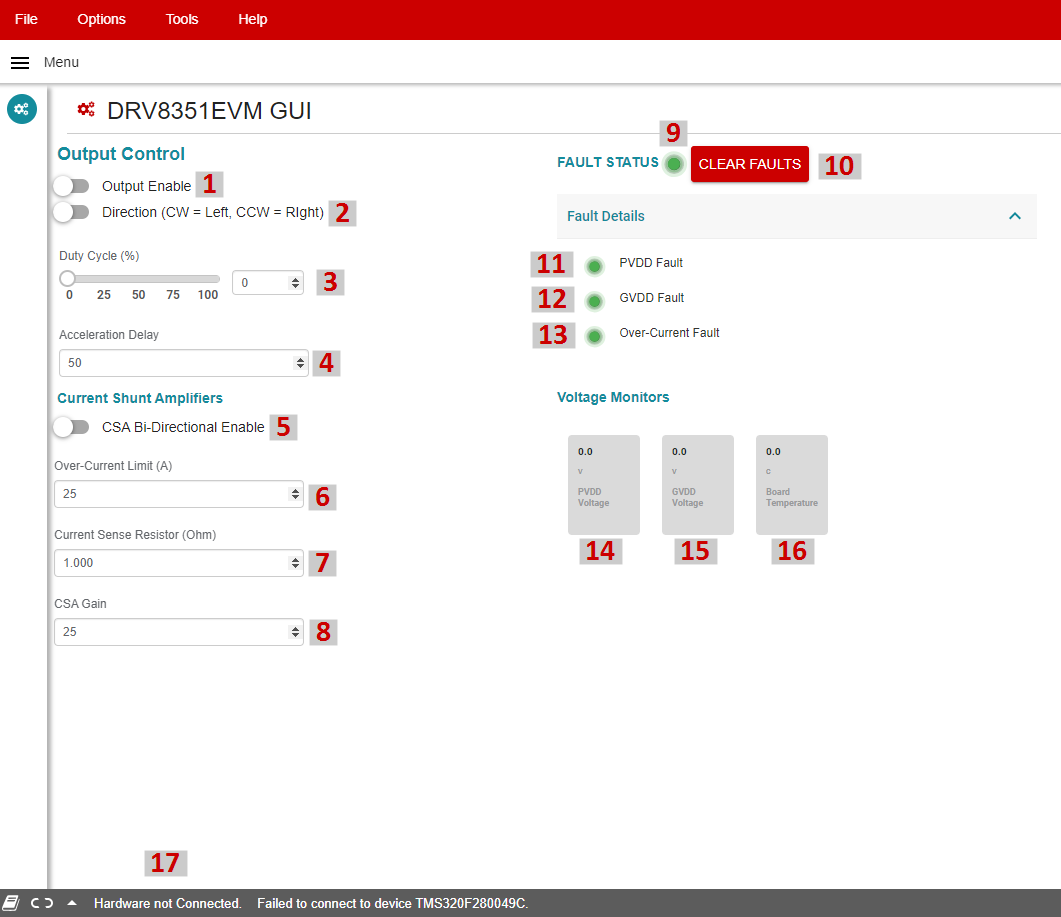
 Figure 3-1 DRV8351EVM GUI
Software
Figure 3-1 DRV8351EVM GUI
SoftwareThe GUI connect to and program the C2000 MCU on the LAUNCHXL-F280049C board when launched, assuming the board is connected and powered.
The GUI includes the following indicators and controls.
| Item # | Item Name | Item Description |
|---|---|---|
| 1 | Output enable | This enables or disables the Duty Cycle slider. When disabled, the Duty Cycle is automatically set to 0%. |
| 2 | Direction | This changes the direction the motor is spinning |
| 3 | Duty cycle % | This controls the Duty Cycle % input sent to the DRV8351. Note that the PWM frequency is fixed at 20kHz. |
| 4 | Acceleration delay | Number of processing cycles to skip in each update of the PWM and GUI controls. Increase this for slower PWM update rate or decrease for faster PWM update rate. |
| 5 | CSA bi-directional enable | Enabled by default, this controls the software offset for the CSA. This must match the selection of jumper J8. |
| 6 | Over-current limit | Software Over-Current limit for gross overcurrent detection and Fault. |
| 7 | Current sense resistor | Current sense resistor value populated on board, default is 0.003 ohms. |
| 8 | CSA gain | CSA gain resistor setting, hardware resistor, default 10V/V. |
| 9 | Fault status LED | Indicator for overall Fault status. Logical OR of all faults. |
| 10 | CLEAR FAULTS | Click this button to clear the Fault warning. If the fault persists, then this control does not disable or clear the faults. |
| 11 | PVDD fault LED | Indicates a PVDD fault has occurred, either overvoltage or undervoltage. |
| 12 | GVDD fault LED | Indicates a GVDD fault has occurred, either overvoltage or undervoltage. |
| 13 | Over-current fault LED | Indicates a gross Over-Current fault has occurred. Limit is set by control (5). |
| 14 | PVDD voltage indicator | PVDD voltage sensed by the MCU. |
| 15 | GVDD voltage indicator | GVDD voltage sensed by the MCU. |
| 16 | Board temperature | Temperature sensor on the bottom of the PCB located under the FETs. |
| 17 | Connection status and control | Displays if the GUI is connected to the hardware. |
Once the hardware is connected, the FAULT Status and Voltage Monitors must match the EVM. If these do not match, then remove EVM power and recheck the setup.
To spin the motor:
- Enable the PWM using the Output Enable toggle switch.
- Use direction to toggle the direction the motor spins.
- Use the Duty Cycle slider or input field to change the PWM Input Duty Cycle.
- The motor now spins.