SLVUCY2 April 2024 DRV8161
3.1 DRV8161 EVM GUI Software
This section details the features of the EVM GUI Software. The GUI is written in GUI Composer and is available on the development software gallery at dev.ti.com/gallery.
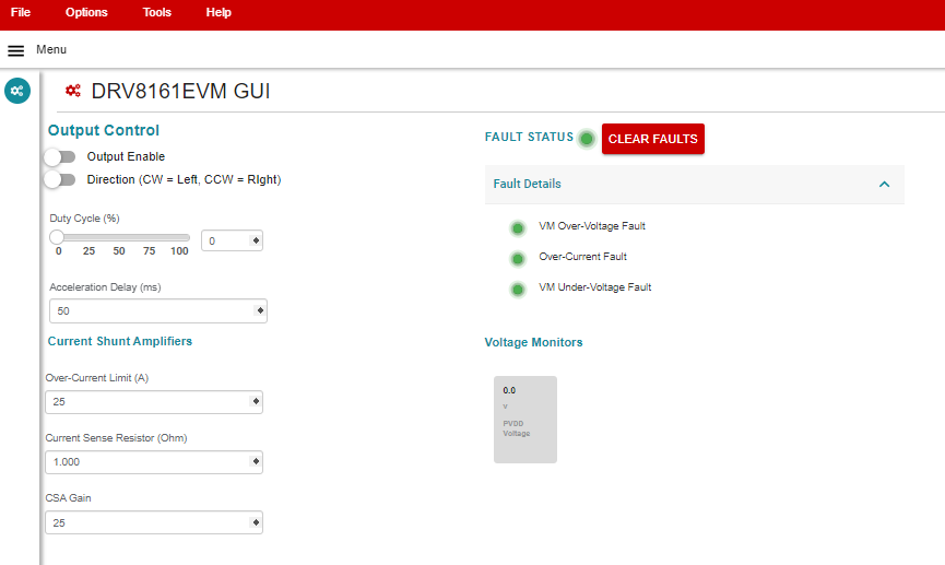
 Figure 3-1 DRV8161EVM GUI
Software
Figure 3-1 DRV8161EVM GUI
SoftwareThe GUI connects and programs the C2000 MCU on the LAUNCHXL-F280049C board when launched, assuming the board is connected and powered. Once the hardware is connected, the FAULT status and voltage monitors match the EVM. If these do not match, then remove EVM power and recheck the setup. If the fault is triggered, then press the Clear Faults button on the GUI.
To spin the motor:
- Using Google Chrome® browser, navigate to https://dev.ti.com/gallery/view/InternalBLDC/DRV8161-EVM-GUI/ver/0.1.4/.
- After loading, make sure that the GUI connects to the board and shows Hardware Connected in the bottom status bar and that the MCU LED is turned on.
- Confirm that the GUI reports VM_Undervoltage Fault and Over-Current Fault
- Turn on the power supply at 24V and 1A limit, board cannot take more than 300mA. (Depending on motor voltage and load.)
- 3.3V, PVDD, and GVDD LEDs lights up green.
- Click the Clear Faults button on the GUI and confirm all faults lights on GUI are cleared (green) and check to see no board FAULT_X LEDs are lit.
- Check the following:
- GUI reads back approximately 24V for the PVDD voltage.
- GUI shows no FAULTs.
- FAULT LEDs is now OFF.
- Toggle Output Enable to ON.
- Raise the Duty Cycle (%) to desired value and the motor starts spinning.
- If direction change is needed, then toggle the direction in the GUI, observe motor slowing down to a stop and then spinning in opposite direction.
- Disable the motor by switching the Output Enable to OFF.
Note: The overcurrent limit is used to set software current limit
(max 30A). Current sense resistor value and gain dependent on what is populated on
the EVM.