SLVUCZ2 May 2024
2.2 Connector Information
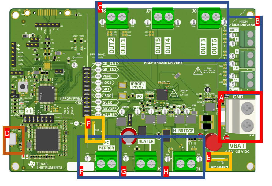
 Figure 2-3 Connectors
Table 2-2 Connectors Description
| Component Label | Description |
|---|---|
| A | Input power supply connector. Power cables can be directly connected to the screw terminals or clipped to the test points on either side of the connector. |
| B | High-side driver output connectors |
| C | Half-bridge output connectors |
| D | USB connector |
| E | Ground strap can be used as ground for probes and other connectors. |
| F | EC mirror output and ground. Ground located on the right side of terminal block. |
| G | Heater output and ground. Ground located on the right side of terminal block. |
| H | H-Bridge outputs. SH1 and SH2 are right side and left side of the terminal blocks respectively. |