SLVUD20 October 2024 DRV8376
2.6 Hardware Variant Configuration
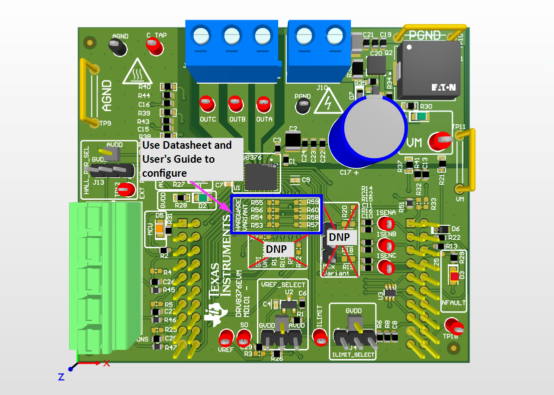
To use the DRV8376EVM using the hardware variant IC, use the tables and figure below to configure the device correctly. Make sure the resistors for SPI variant and MCx variant are unpopulated or DNP.
 Figure 2-12 Hardware Configuration
Resistors
Figure 2-12 Hardware Configuration
ResistorsTable 2-3 PWM and ASR/AAR Mode
Configuration
| MODE Type | PWM MODE | ASR and AAR Mode | MODE_SR Pin | DRV8376EVM |
|---|---|---|---|---|
| Mode 1 | 6x Mode | ASR and AAR disabled | Connected to AGND | Populate R57 with 0 ohm resistor or short |
| Mode 2 | 6x Mode | ASR and AAR enabled | Hi-Z | Populate R57 with >200k ohm resistor |
| Mode 3 | 3x Mode | ASR and AAR disabled | Connected to GVDD with 47 kohm resistor | Populate R53 with 47 k ohm resistor |
| Mode 4 | 3x Mode | ASR and AAR enabled | Connected to GVDD | Populate R53 with 0 ohm resistor or short |
Table 2-4 Slew Rate
Configuration
| Slew Rate | SLEW Pin | DRV8376EVM |
|---|---|---|
| 1100V/us | Connect to AGND | Populate R60 with 0 ohm resistor or short |
| 500V/us | Hi-Z | Populate R60 with >200k ohm resistor |
| 250V/us | 47 k ohm to GVDD | Populate R56 with 47 k ohm resistor |
| 50V/us | Connect to GVDD | Populate R56 with 0 ohm resistor or short |
Table 2-5 Gain Configuration
| Gain | Gain Pin | DRV8376EVM |
|---|---|---|
| 0.4V/V | Connect to AGND | Populate R58 with 0 ohm resistor or short |
| 1V/V | Hi-Z | Populate R58 with >200k ohm resistor |
| 2.5V/V | 47 k ohm to GVDD | Populate R54 with 47 k ohm resistor |
| 5V/V | Connect to GVDD | Populate R54 with 0 ohm resistor or short |
Table 2-6 OCP Configuration
| OCP | OCP Pin | DRV8376EVM |
|---|---|---|
| 4.5A | Connect to AGND | Populate R59 with 0 ohm resistor or short |
| 2A | Connect to GVDD | Populate R55 with 0 ohm resistor or short |